CHARACTERIZATION OF A RESONATOR
Resonators (and indeed, interferometers for the most part) may be characterized in terms of frequency or wavelength behavior by a number of parameters, including finesse and free spectral range. In terms of optical loss, two additional parameters are now introduced which characterize the resonator: the total loss coefficient (γr) and the photon lifetime (τc). Individual resonator losses occur because of absorption and scattering in the lasing medium itself, at tube windows, as a result of unintended loss at the HR and as an intended loss at the OC which forms the output beam. It is useful to express losses as coefficients with units of m-1 (per meter). This may seem counterintuitive since the loss caused by a mirror occurs at a single point in a laser and is not spread out across the entire tube as this approach should do, but the use of this gamma notation shall become evident as.
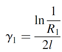
Losses at each mirror are expressed as loss coefficients (γ1 for one mirror and γ2 for the other mirror) as if the loss was distributed throughout the entire laser:
 (1.1)
(1.1)
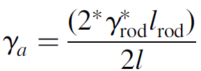
where R1 is the reflectivity of the mirror. You will note that this is of the same form as the gain threshold. The other primary loss, due to absorption or scattering in the lasing medium, and designated γa, is usually given as a property of the medium itself in units of m-1 or cm-1. Where the gain medium spans the entire distance between cavity mirrors, such as the case with most helium–neon gas lasers, one may simply use this number directly; however, where the gain medium is shorter than the cavity, e.g., in a solid state laser where the rod is relatively short in length, we must spread out the loss across the cavity as per the following approximation:
 (1.2)
(1.2)
In this case the numerator evaluates to the (dimensionless) total loss for a round-trip through the rod which is then spread out across the length of the cavity (2l). In a solid-state laser this would not compensate for the index of refraction of the rod which leads to an apparent length (optically speaking) of n*rod lrod; but for most practical lasers the rod is much shorter than the total cavity length and so the cavity is mainly air with n =1.00: So now an overall distributed-loss coefficient (γr) can be used to describe the total cavity losses as
γr = γa + γ1+ γ2 (1.3)
Such a coefficient, a distributed-loss coefficient, sums all losses in the resonator and has units of m-1. It is useful in further calculations of resonator parameters, as we show below.
Photon lifetime (τc) refers to the average time that a photon spends in the cavity of a laser before passing through the OC and becoming part of the output beam or being absorbed in the lasing medium itself. It is best illustrated by an example in which a simple laser cavity consists of one fully reflecting mirror and one mirror of 98% reflectivity (and otherwise is essentially lossless). If the mirrors are separated by 50 cm, the expected photon lifetime is
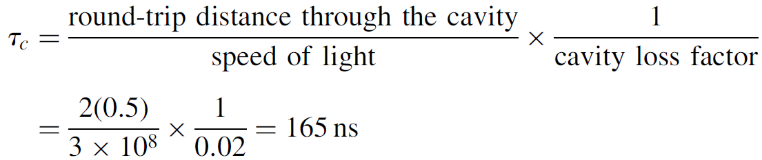
While the photon takes only 3.3 ns to traverse the entire 1-m round trip of the cavity, the probability of passing through the OC is low since it has high reflectivity. On average, then, a photon will make 50 such round trips before exiting the cavity.
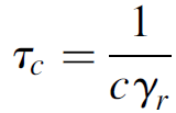
Because we have defined the cavity loss factor as a function of length (in m-1), the product of the loss factor with the speed of light (in m/s) defines the loss of photons per unit time (in s-1), so the expression for photon lifetime simplifies to
 (1.4)
(1.4)
This relation is, once again, useful in further calculations involving energy storage in a laser cavity. Finally, photon lifetime is also related to the spectral linewidth of laser output by
 (1.5)
(1.5)
Mathematically, this is simply the Fourier transform relationship between frequency and time (e.g., the Fourier transform of an infinitely narrow pulse in the time domain is a broadband output covering the entire spectrum of available frequencies). This is also a mechanism by which laser lines are broadened, called lifetime broadening.


