تاريخ الفيزياء
علماء الفيزياء


الفيزياء الكلاسيكية
الميكانيك
الديناميكا الحرارية
الكهربائية والمغناطيسية
الكهربائية
المغناطيسية
الكهرومغناطيسية
علم البصريات
تاريخ علم البصريات
الضوء
مواضيع عامة في علم البصريات
الصوت
الفيزياء الحديثة
النظرية النسبية
النظرية النسبية الخاصة
النظرية النسبية العامة
مواضيع عامة في النظرية النسبية
ميكانيكا الكم
الفيزياء الذرية
الفيزياء الجزيئية
الفيزياء النووية
مواضيع عامة في الفيزياء النووية
النشاط الاشعاعي
فيزياء الحالة الصلبة
الموصلات
أشباه الموصلات
العوازل
مواضيع عامة في الفيزياء الصلبة
فيزياء الجوامد
الليزر
أنواع الليزر
بعض تطبيقات الليزر
مواضيع عامة في الليزر
علم الفلك
تاريخ وعلماء علم الفلك
الثقوب السوداء
المجموعة الشمسية
الشمس
كوكب عطارد
كوكب الزهرة
كوكب الأرض
كوكب المريخ
كوكب المشتري
كوكب زحل
كوكب أورانوس
كوكب نبتون
كوكب بلوتو
القمر
كواكب ومواضيع اخرى
مواضيع عامة في علم الفلك
النجوم
البلازما
الألكترونيات
خواص المادة
الطاقة البديلة
الطاقة الشمسية
مواضيع عامة في الطاقة البديلة
المد والجزر
فيزياء الجسيمات
الفيزياء والعلوم الأخرى
الفيزياء الكيميائية
الفيزياء الرياضية
الفيزياء الحيوية
الفيزياء العامة
مواضيع عامة في الفيزياء
تجارب فيزيائية
مصطلحات وتعاريف فيزيائية
وحدات القياس الفيزيائية
طرائف الفيزياء
مواضيع اخرى

GAIN AND LOSS IN A CAVITY
 المؤلف:
Mark Csele
المؤلف:
Mark Csele
 المصدر:
FUNDAMENTALS OF LIGHT SOURCES AND LASERS
المصدر:
FUNDAMENTALS OF LIGHT SOURCES AND LASERS
 الجزء والصفحة:
p160
الجزء والصفحة:
p160
 17-3-2016
 1853
1853


+
-
20
GAIN AND LOSS IN A CAVITY
Assume that a laser operates with an output of 1 mW and has an output coupler with a reflectivity of 99.0% (and hence a transmission of 1.0%). This implies that the power circulating inside the cavity (the circulating power) is 100 mW. Of course, such intracavity power level is not usable: It is required to keep the rate of stimulated emission large enough and hence sustain laser action. The output beam (defined by the transmissivity of the output coupler) represents a loss in a laser cavity. Other losses include absorption and scattering in the laser medium itself and losses at windows terminating the lasing medium (e.g., windows on a gas laser plasma tube). Most laser gain media have low gains, so it is essential that losses be kept to a minimum. Since the output coupler represents a loss, the amount of transmissivity depends on the gain of the laser. When total losses in the laser exceed the gain of the medium, the laser will fail to oscillate.
An experiment in which a variable loss (a glass slide) is inserted into the cavity of a He Ne laser. Let us reexamine the experiment by plotting the output power (which is, of course, proportional to circulating power) against loss in the cavity, as shown in Figure 1.1. Circulating power is easily measured simply by measuring laser output and multiplying by the transmission of the OC. In this experiment the OC has a transmission of 1.0%, so that for a measured output of 370 μW, the intracavity circulating power is 37 mW. The maximum inserted loss that may be tolerated in this laser is found to be 1.2%. When this loss is summed with other losses in the laser, such as absorption in the medium itself and the loss of the OC (1.0%), the gain of the laser medium may be calculated.
It is obvious from Figure 1.1 that even small losses have a large effect on the output power of a laser losses in a real laser must thus be kept as low as possible. Where possible, such as in a He Ne laser, mirrors are often sealed directly into the ends of the tube so that there are no windows in the optical path to increase loss. In many lasers, though, cavity mirrors must be isolated from the discharge to prevent attack from the plasma. Use of external optics is also required when a laser uses a wavelength selector. In these cases the ends of the plasma tube must be capped with an optical window. To minimize losses, optical windows are angled at
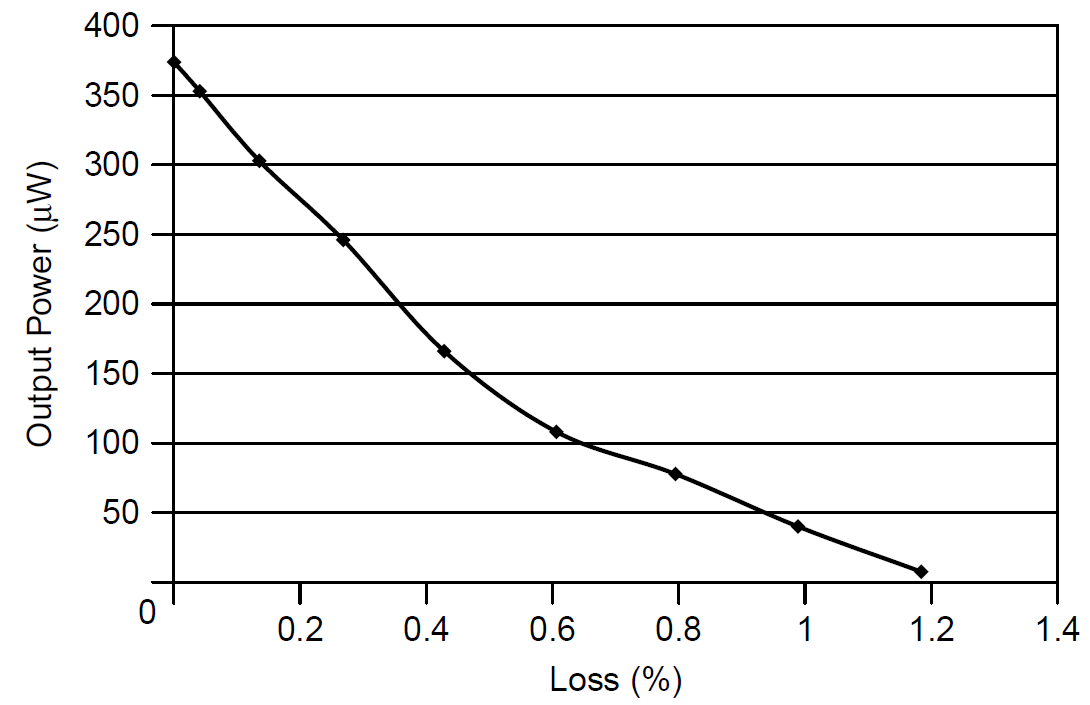
Figure 1.1. Effect of cavity loss on output power in a laser.
the Brewster angle, which polarizes the output of the laser since loss is essentially zero in one polarization and very significant in the other polarization.
Figure 1.2 shows a Brewster window on a small air cooled argon laser tube. Protruding from the anode of this tube (with attached cooling fins visible in the
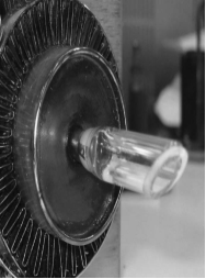
Figure 1.2. Brewster window in a gas laser.
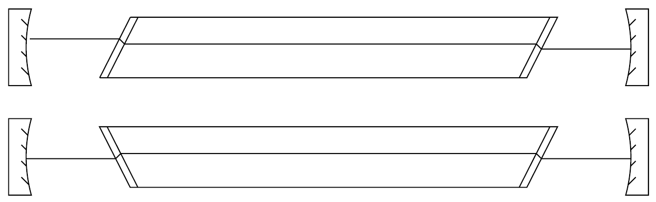
Figure 1.3. Brewster window in a gas laser.
photograph) is a metal tube that is fused to a quartz tube sealed with a quartz window. The window is angled at Brewster’s angle. Most tubes contain two windows, one at each end of the tube, and each must be aligned in the same optical axis. As Figure 1.3 shows, where two Brewster windows are used, they should be oriented such that the intracavity beam does not shift overall position as it passes through both windows (as in the top diagram). The optimal angle can be determined from the Fresnel equation as the angle at which reflection (Rp) is reduced to zero. This angle depends on the index of refraction of the window material itself according to
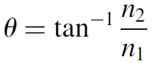 (1.1)
(1.1)
where n2 is the index of refraction of the window and n1 is the index of refraction of the surrounding media (1.00 for air and most gases). Hence Brewster’s angle is independent of the wavelength of the laser except that the index of refraction of the window may change as a function of wavelength, so for a multiple-wavelength laser such as an argon laser, the angle will be optimal for only one wavelength, with slightly higher losses at other wavelengths (only slightly higher since the index of refraction will not change much). The optimal output coupling can be calculated as a function of the gain of the device and total losses in the cavity. By reducing losses in the cavity such as those at tube windows, power output may be enhanced and weak transitions may be allowed to laser.
 قسم الشؤون الفكرية يصدر مجموعة قصصية بعنوان (قلوب بلا مأوى)
 قسم الشؤون الفكرية يصدر مجموعة قصصية بعنوان (قلوب بلا مأوى)
 قسم الشؤون الفكرية يصدر كتاب (سر الرضا) ضمن سلسلة (نمط الحياة)