

 الفيزياء الكلاسيكية
 الكهربائية والمغناطيسية
 علم البصريات
 الفيزياء الحديثة
 النظرية النسبية
 الفيزياء النووية
 فيزياء الحالة الصلبة
 الليزر
 علم الفلك
 المجموعة الشمسية
 الطاقة البديلة
 الفيزياء والعلوم الأخرى
 مواضيع عامة في الفيزياء
|
Read More
Date: 24-5-2016
Date: 22-10-2020
Date: 17-5-2017
|
NPN AND PNP
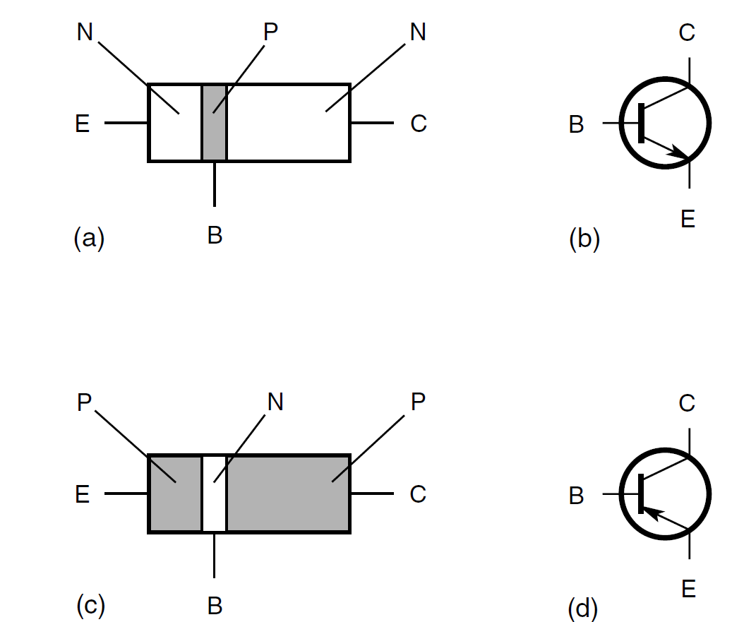
A simplified drawing of an npn transistor and the symbol that is used to represent it in schematic diagrams are shown in Fig. 1. The p-type, or center, layer is the base. The thinner of the n-type semiconductors is the emitter, and the thicker is the collector. Sometimes these are labeled B, E, and C in schematic diagrams, but the transistor symbol indicates which is which (the arrow is at the emitter). A pnp transistor (parts c and d) has two p-type layers, one on either side of a thin n-type layer. In the npn symbol, the arrow points outward. In the pnp symbol, the arrow points inward.
Generally, pnp and npn transistors can perform identical tasks. The only difference is the polarities of the voltages and the directions of the currents. In most applications, an npn device can be replaced with a pnp device, or vice versa, and the power-supply polarity reversed, and the circuit will still work if the new device has the appropriate specifications.
There are various kinds of bipolar transistors. Some are used for rf amplifiers and oscillators; others are intended for audiofrequencies (af). Some can handle high power for rf wireless transmission or af hi-fi amplification, and others are made for weak-signal rf reception, microphone preamplifiers, and transducer amplifiers. Some are manufactured for switching, and others are intended for signal processing.

Fig. 1. Pictorial diagram of npn transistor (a), schematic symbol for npn transistor (b), pictorial diagram of pnp transistor (c), and schematic symbol for pnp transistor (d).


|
|
|
|
دراسة: حفنة من الجوز يوميا تحميك من سرطان القولون
|
|
|
|
|
|
|
تنشيط أول مفاعل ملح منصهر يستعمل الثوريوم في العالم.. سباق "الأرنب والسلحفاة"
|
|
|
|
|
|
|
لتعزيز التواصل مع الزائرات الأجنبيات : العتبة العلويّة المقدّسة تُطلق دورة لتعليم اللغة الإنجليزية لخادمات القسم النسويّ
|
|
|