تاريخ الفيزياء

علماء الفيزياء


الفيزياء الكلاسيكية

الميكانيك

الديناميكا الحرارية


الكهربائية والمغناطيسية

الكهربائية

المغناطيسية

الكهرومغناطيسية


علم البصريات

تاريخ علم البصريات

الضوء

مواضيع عامة في علم البصريات

الصوت


الفيزياء الحديثة


النظرية النسبية

النظرية النسبية الخاصة

النظرية النسبية العامة

مواضيع عامة في النظرية النسبية

ميكانيكا الكم

الفيزياء الذرية

الفيزياء الجزيئية


الفيزياء النووية

مواضيع عامة في الفيزياء النووية

النشاط الاشعاعي


فيزياء الحالة الصلبة

الموصلات

أشباه الموصلات

العوازل

مواضيع عامة في الفيزياء الصلبة

فيزياء الجوامد


الليزر

أنواع الليزر

بعض تطبيقات الليزر

مواضيع عامة في الليزر


علم الفلك

تاريخ وعلماء علم الفلك

الثقوب السوداء


المجموعة الشمسية

الشمس

كوكب عطارد

كوكب الزهرة

كوكب الأرض

كوكب المريخ

كوكب المشتري

كوكب زحل

كوكب أورانوس

كوكب نبتون

كوكب بلوتو

القمر

كواكب ومواضيع اخرى

مواضيع عامة في علم الفلك

النجوم

البلازما

الألكترونيات

خواص المادة


الطاقة البديلة

الطاقة الشمسية

مواضيع عامة في الطاقة البديلة

المد والجزر

فيزياء الجسيمات


الفيزياء والعلوم الأخرى

الفيزياء الكيميائية

الفيزياء الرياضية

الفيزياء الحيوية

الفيزياء العامة


مواضيع عامة في الفيزياء

تجارب فيزيائية

مصطلحات وتعاريف فيزيائية

وحدات القياس الفيزيائية

طرائف الفيزياء

مواضيع اخرى
CALCULATING THRESHOLD GAIN
المؤلف:
Mark Csele
المصدر:
FUNDAMENTALS OF LIGHT SOURCES AND LASERS
الجزء والصفحة:
p106
10-3-2016
14053
CALCULATING THRESHOLD GAIN
When the laser is operating at steady-state conditions (i.e., constant optical power output), the net gain in the laser must be 1. If the net gain were greater than 1, the output power would increase. Net gains below 1 cause the output power to drop until the laser ceases to operate. So consider, then, a round trip by a stream of photons in the tube (Figure 1.1). The power after the round trip must equal the power before the round trip. Sure, the photon stream gains energy (through laser gain), but just as much power as is gained is lost through absorption in the medium, in addition to the portion extracted as the output beam.
The power gained during the round trip is exp(g . 2x), where 2x is the total path length of the laser (x is the length of the gain medium through which the stream of photons passes twice). The power lost during the same trip is exp(-γ . 2x), where γ

Figure 1.1. Gain and loss in a round trip through a laser.
is a new term describing all losses in the cavity due to the lasing mechanisms, with the exception of the mirrors themselves. The losses from the mirrors themselves will be seen as the reflectivities of the two mirrors, labeled R1 and R2. A perfect mirror, with 100% reflection, has an R value of 1.
Equating these parameters for a round trip through the tube yields
net gain = laser gain × loss × loss at mirror 1 × loss at mirror 2 = exp(2gx) exp(-γ . 2x)R1R2 (1.1)
Knowing R1 and R2 as well as γ, we can solve for gain, which must equal 1 for an operating laser. This gain will be the threshold gain, the gain required to allow the laser to operate in this steady-state condition:
 (1.2)
(1.2)
where x is the length of the gain medium. In many lasers the gain of the laser medium is proportional to the pump energy (but not without limits, as we shall see). A minimum pump energy will hence be required to generate a gain of at least the threshold value in order for lasing to begin.
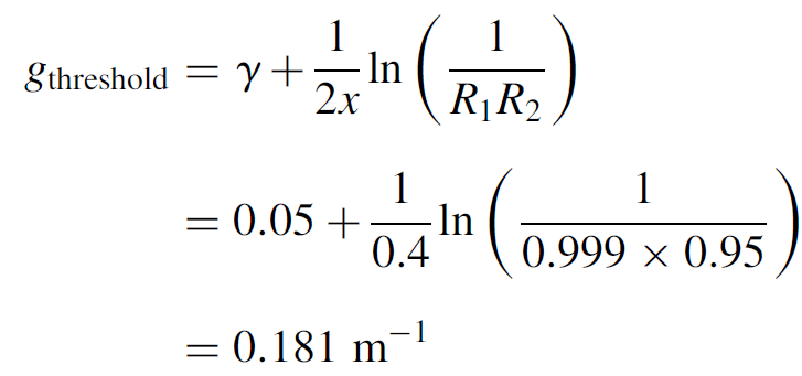
Example 1.1 Gain and Loss in a He Ne Laser As an application of the threshold gain formula, consider a helium–neon laser in which the loss is known to be 0.05 m-1. The laser has an actual plasma tube length (where gain occurs, not the entire length of the tube between mirrors) of 20 cm. One mirror is 99.9% reflecting, and the output coupler is 95% reflecting. Calculate the threshold gain for the tube.
SOLUTION Using equation (1.2), we can substitute as follows:

This is an excessively high gain requirement for a He Ne laser, and the laser would probably not oscillate. To allow the laser to work, either the plasma tube must be made longer than 20 cm or the reflectivity of the output coupler must be increased to better than 95%.
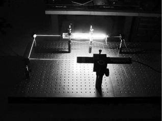
Threshold gain has many practical applications such as determining the minimum required reflectivities of cavity optics as well as allowed insertion losses in the cavity. One can experimentally measure the gain and loss of a lasing medium directly. One simple method (for a helium–neon laser) is to pass the light from an operating helium–neon laser directly through the bore of a bare plasma tube (windows on each end rather than the usual integral mirrors). As the beam from the first laser passes through the plasma tube, it is amplified. By measuring the power of the exiting beam with the bare tube both energized and not energized (and knowing the length of the gain medium) the gain of the medium can be measured directly, giving a useful value for g. This is called a MOPA (master oscillator, power amplifier) configuration, the first laser being the oscillator and the second, the amplifier. It is used in many industrial lasers (e.g., Nd: glass) to generate enormous power levels but is useful here for experimentation. Figure 1.2 depicts an experimental setup of this type, and Figure 1.3 shows an actual experimental setup in which the probe laser is on the bottom of the photograph and the beam is steered by two mirrors to pass through the gain tube. Upon exit from the gain tube, power is measured using an optical power meter.
One can measure the gain of any transition this way simply by using a pump beam at the desired wavelength. Obviously, the oscillator laser must have exactly the same wavelength as the transition whose gain we are attempting to measure, so we would always use the same type of laser (a He Ne laser to measure amplification of a He Ne tube, argon for an argon tube, etc). He Ne lasers have relatively large gains at the red transition (632.8 nm) but much smaller gains at the other allowed lasing transitions, such as the green (543 nm) or orange (612 nm). Not visible in Figure 1.3 is the fact that the probe beam is green. This illustrates a major advantage

Figure 1.2. Experimental setup for measuring the gain of a laser directly.
of this technique, as one can measure the gain of any transition by selecting a laser (the oscillator) of the wavelength desired for the transition to be measured. In the case of helium–neon lasers operating at wavelengths other than red (which have lower gains at these wavelengths), the optical elements for these lasers must have extremely low losses. As well, the output coupler has a much lower transmission than a red laser would have. Green helium–neon lasers have much lower output powers than those of similar-size red laser tubes.
The technique just described works with a variety of lasers, including argon-ion and YAG lasers, but a second (and somewhat simpler) method for measuring gain is to insert a variable loss into the cavity of a working laser. In its simplest form, this loss may be a slide of glass at a certain angle. At Brewster’s angle, for example, there will be zero loss, as least in one polarization. By varying the angle to the point where lasing is extinguished, one may determine the value of the inserted loss. Summing other losses in the laser, such as that of the output coupler (OC), loss at tube windows, and attenuation in the tube itself, one may then calculate the gain of the lasing medium.

Figure 1.3. Actual experimental setup for measuring gain.

Figure 1.4. Second experimental method to determine laser gain.
Figure 1.4 shows an experimental setup in the author’s lab in which a He Ne tube with external mirrors is set up on an optical breadboard. The photo details the variable loss, which is a glass slide on a rotating stage. The slide is rotated until the laser ceases to oscillate. That angle is now substituted into Fresnel equations to yield an answer in terms of inserted loss. Given the angle θ of the glass slide, the angle of the beam inside the glass itself (with index of refraction n) may be found by using Snell’s law as follows:
 (1.3)
(1.3)
where the subscript i represents the incident ray and r the refracted ray. The reflection (loss) in both polarizations may now be found by using the Fresnel equations:
 (1.4)
(1.4)
 (1.5)
(1.5)
The polarization Rp is parallel to the Brewster window and so is the polarization of concern here. The other polarization (Rs) yields a minimum loss of about 6%, which is far too high to allow laser oscillation in that plane (at least with a small laser with a small gain such as the one employed here). In the process of inserting this loss, we have highly polarized the output beam.

Figure 1.5. Reflective loss as a function of angle for an intracavity glass slide.
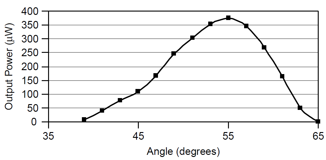
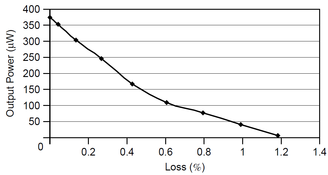
Using the Fresnel equations, we can determine the loss of the glass slide (the reflectivity) as a function of angle (for one polarization only); this is plotted in Figure 1.5. It must be remembered that this loss is for each glass-to-air interface, so these figures must be multiplied by 2 for a single pass through the slide. Inserting this variable loss into the cavity between the plasma tube and any one cavity mirror, we find the output power as a function of θ, portrayed in Figure 1.6. Like Figure 1.5, the loss increases more rapidly on the large-angle side, so the output power decreases more rapidly on that side. Finally, power output as a function of inserted loss from this slide is plotted in Figure 1.7. You are reminded again that the inserted loss is for one surface only: The actual slide has two surfaces, so this value must be multiplied by 2.
Example 1.2 Gain of a Real He Ne Laser Consider the setup in Figure 1.4, in which a glass slide with an index of refraction of 1.46 is used as a variable loss. When the glass slide is at Brewster’s angle, the maximum laser output will appear, but as the slide is rotated at an angle away from Brewster’s angle, lasing is observed to cease at 45.5 degrees. We now find the loss caused by the inserted slide using the Fresnel equation. Using Snell’s law (n1/n2 = sinθ1/ sinθ2) the

Figure 1.6. Power output as a function of angle.

Figure 1.7. Power output as a function of inserted loss.
angle of refraction in the glass slide is found to be 29.69 degrees. This is then substituted into the Fresnel equation (with n1 = 1.000 for air) for reflectivity in the parallel plane:
 (1.6)
(1.6)
Squaring the reflection coefficient to get the intensity coefficient, the reflectivity at this angle is found to be 0.00560. This is for a single surface, so the reflection loss for one pass through the slide is 0.0112.
Summing this loss with other losses in the laser, and knowing that gain equals loss at the point where the laser just begins to oscillate, we may determine gain of the laser. Consider a round trip through the laser, which consists of two passes through the plasma tube (i.e., two gains), one reflection (loss) off each cavity mirror, four passes through the tube windows (one at each end of the tube), and two passes through the variable loss element:

Typical values for loss in a He Ne laser include:
● Loss at the OC of 1.0% (the transmission of the mirror)
● Loss at the high reflector (HR) is negligible (the reflectivity is better that 99.9995% so the loss is less than 0.0005%).
● Attenuation of the laser medium itself is approximately 0.05 m21, so for a 35-cm tube, it is 0.0175.
● Loss at each window is approximately 0.25% per pass (plane, A/R-coated windows; this figure will change if the tube features Brewster windows, as most argon lasers do).
Total losses sum to 0.0817, and since the gain is equal to this figure (for two passes through the plasma tube), the gain is calculated to be 0.0408 for a single pass through the tube. The gain medium itself, not the length of the tube, but rather that of the actual inner plasma tube where amplification occurs, is 29.5 cm in this particular case, so the gain is determined to be 0.138 m-1. This is typical for a small He Ne laser.
 الاكثر قراءة في بعض تطبيقات الليزر
 اخر الاخبار
اخبار العتبة العباسية المقدسة

الآخبار الصحية


 قسم الشؤون الفكرية يصدر كتاباً يوثق تاريخ السدانة في العتبة العباسية المقدسة
 "المهمة".. إصدار قصصي يوثّق القصص الفائزة في مسابقة فتوى الدفاع المقدسة للقصة القصيرة
 (نوافذ).. إصدار أدبي يوثق القصص الفائزة في مسابقة الإمام العسكري (عليه السلام)


