


 تاريخ الرياضيات
 الرياضيات في الحضارات المختلفة
 الرياضيات المتقطعة
 الجبر
الجبر
 الهندسة
 المعادلات التفاضلية و التكاملية
 التحليل
 علماء الرياضيات
 |
Read More
Date: 23-2-2019
Date: 1-1-2017
Date: 7-1-2017
|
It has been shown that every seriesparallel circuit corresponds to a Boolean function and conversely that every Boolean function corresponds to a series-parallel circuit. Boolean functions can also be found which reflect the properties, although not the geometry, of other types of circuits. We will present three methods of writing a Boolean function for such circuits. The converse of this problem, that of finding a non-series-parallel circuit for a given function, will be discussed only partially. In fact, no general solution is known except in the special case of symmetric circuits, which will be treated in a later section.
So far we have discussed 2-terminal circuits only. One may think of such a circuit as being designed to control the operation of a light connected in series with a battery and the given circuit. Changes made in simplification are such that the set of positions which will cause the light to shine are not altered. Such changes correspond to exactly those simplifications of the associated function allowable within a Boolean algebra. We must introduce the concept of an n-terminal circuit. Fig. 1-1 shows a 3-terminal circuit. This circuit is simply a combination of three

FIG. 1-1. A 3-terminal circuit.
2-terminal circuits. We may think of this circuit as controlling a light by any of the three circuits joining points labelled T1, T2, and T3. We may designate the various functions as follows: f12 will denote the 2- terminal circuit joining T1 to T2; f13 that joining T1 to T3; and f23 that joining T2 to T3. We could, of course, visualize this circuit as simultaneously controlling the operations of three light bulbs, each with different operating characteristics in terms of the positions of the switches involved.
In general, an n-terminal circuit will be defined as a configuration of switches connected by wires in which n points are designated as terminals. The 1/2n(n - 1) possible functions are designated f2 denoting the function corresponding to the 2-terminal circuit joining Ti to Tj for each i and j, where i≠j; but otherwise i and j may assume any pair of values from 1 to n inclusive. Two such circuits are equivalent if each pair of 2-terminal circuits are equivalent or, as well, if the functions representing the pairs of corresponding circuits are equal.
As in ordinary circuit theory, there exist wye-to-delta and delta-to-wye transformations. We introduce these transformations to develop a method for reducing a non-series-parallel circuit to an equivalent circuit of seriesparallel type. (The method actually depends only on the wye-to-delta transformation. The other is included only as a matter of interest.) We shall define a wye circuit as a 3-terminal circuit, where the three 2-terminal circuits involved have a common point other than a terminal. A delta circuit is a 3-terminal circuit in which the only common points of any pair of the three 2-terminal circuits are the three terminals, each of which is common to exactly two of the 2-terminal circuits.
The wye-to-delta transformation is shown in Fig. 1-2. That the wyeto-delta transformation gives an equivalent circuit is immediately apparent from noting that the 2-terminal circuits formed in each case are series connections of the same pairs of switches.
The delta-to-wye transformation is shown in Fig. 1-3. That the deltato-wye transformation gives an equivalent circuit follows from the distributive law for (+) over (.)For example, f12 = x + zy = (x + Z) (X + y),
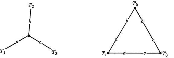
Fig. 1-2. Wye-to-delta transformation.
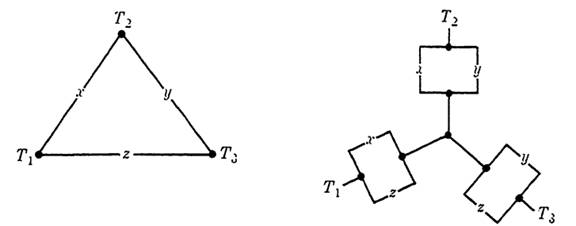
Fig. 1-3 Delta-to-wye transformation.
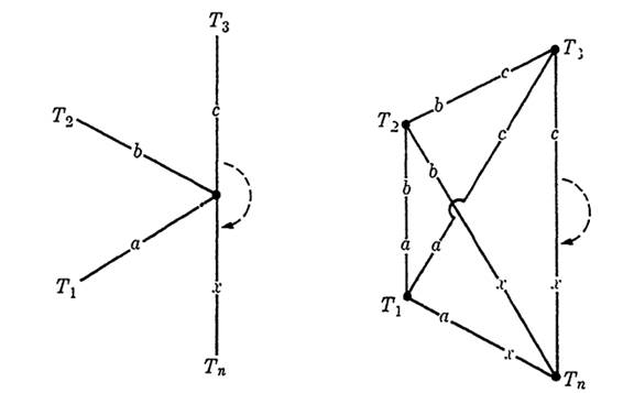
Fig. 1-4 Star-to-mesh transformation.
where the first form represents the delta circuit, and the second represents the wye circuit.
The wye-to-delta transformation may be generalized to a star-to-mesh transformation, where the star represents an n-terminal circuit with a common central point which is eliminated to give an equivalent mesh circuit. Figure 1-4 suggests the method employed. That this transformation produces an equivalent circuit is self-evident, although a formal proof by induction may be given. It can also be shown that if the original circuit contains a single n-point star but no m-point star, for m > n, the new circuit will contain no star with more than n - 1 points. Hence, a systematic reduction is possible, leading to a circuit with no stars at all, that is, a series-parallel circuit.
As an application of the wye-to-delta transformation, consider the problem of finding a Boolean function to represent the bridge circuit of Fig. 1-5, a non-series-parallel circuit. The vertices of the circuit are labelled with capital letters for reference. The point Q is the central point
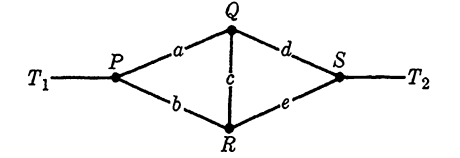
FIG. 1-5. A bridge circuit.

FIG. 1-6. Transformed circuit for the bridge of Fig. 1-5.
of a wye circuit with terminals P, R, and S. Applying the wye-to-delta transformation gives an equivalent circuit shown in Fig. 1-6(a), redrawn for convenience in Fig. 1-6(b). From this figure, it follows that the bridge circuit of Fig. 1-5 is represented by the Boolean function f12 = ad + (ac + b) (cd + e), even though the function does not suggest the geometry of the given circuit. Conversely, we may say that if any function corresponds exactly to f in form, it is possible to use a bridge circuit to repre- sent the function. It is obvious that to identify a combination of this type in a given Boolean function is not easy.
The method presented in the preceding paragraph generalizes with the use of the star-to-mesh transformations to find a method for obtaining a Boolean function for any given circuit, series-parallel or not, and for complicated circuits is probably better than either of the following methods.
Two alternative methods of obtaining the Boolean function for a circuit are easier to use in simple cases, but have the disadvantage of being essentially trial-and-error methods and hence subject to error in complicated cases. The first of these consists of examining the circuit for all possible combinations of closed switches which allow a current through the circuit. Broken lines in Fig. 1-7 illustrate this method. These paths for the bridge circuit correspond to the combinations ad, be, ace, and bcd. The function f12 may then be written as f12 = ad + be + ace + bcd, which is clearly equal to the function obtained previously.
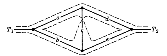
FIG. 1-7. Possible paths in a bridge circuit.

FIG. 1-8. Possible breaks in a bridge circuit.
The second alternative method (the third method to be considered) is illustrated in Fig. 1-8. In this method, broken lines through the circuit are drawn in all possible ways in which the circuit may be broken (by a combination of open switches). These combinations are a, b; d, e; a, c, e; and b, c, d. An alternative form for the function is then given by f12 = (a + b) (d + e) (a + c + e) (b + c + d), which has the value 0 if any of the four sets of switches is open. This form is easily shown to be equal to the two previous forms for f12.
Any of these three methods can be made a basis for the problem of determining whether a function f can be realized by a non-series-parallel circuit. For such a method, one would first examine the properties of various types of such circuits, for example the bridge of Fig. 1-5. These properties could be given in a table or by a special form for the corresponding function. Then the given Boolean function could be compared for possible similarity with the bridge function or table. (See Example 2 below.) Such a method is difficult to apply, but Boolean functions are not well-adapted to more direct methods, since the operations refer directly only to series-parallel circuits.
It should be mentioned that even where a bridge circuit exists, it is not always simpler than an equivalent series-parallel circuit. (See Example 1 below.) In some cases, then, searching for a bridge circuit may be a waste of time.
EXAMPLE 1. Simplify the circuit in Fig. 1-9(a).
Solution. Using method 3,
f12 = (x'y+x+z)(x+z)(x'y+y+z)(x+z+y+x) = xy+z,
and the circuit is therefore equivalent to the circuit in Fig. 1-9(b).
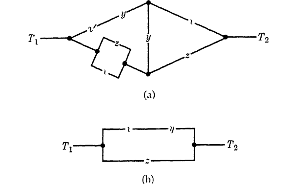
Fig. 1-9

Fig. 1-9
EXAMPLE 2. Draw a bridge circuit for the function
f = (x'u+x'v's+yu+ yvs)(x'+z+w'+v's)(y+z+w'+u).
Solution. Expanding f, we find by comparison with method 2 that we can write f as
f = x'u + yv's + x' (z + w')v's + y(z + w')u.
Hence, f is realized by the bridge of Fig. 1-5 if we let a = x', b = y, c = z + w', d = u, and e = v's. The circuit is shown in Fig. 1-9.

|
|
|
|
دراسة: حفنة من الجوز يوميا تحميك من سرطان القولون
|
|
|
|
|
|
|
تنشيط أول مفاعل ملح منصهر يستعمل الثوريوم في العالم.. سباق "الأرنب والسلحفاة"
|
|
|
|
|
|
|
تثميناً لجهودهم.. العتبة العباسية المقدسة تكرِّم اللجنة التحكيمية والجهات المساهمة بمسابقة فنِّ الخطابة
|
|
|