تاريخ الفيزياء

علماء الفيزياء


الفيزياء الكلاسيكية

الميكانيك

الديناميكا الحرارية


الكهربائية والمغناطيسية

الكهربائية

المغناطيسية

الكهرومغناطيسية


علم البصريات

تاريخ علم البصريات

الضوء

مواضيع عامة في علم البصريات

الصوت


الفيزياء الحديثة


النظرية النسبية

النظرية النسبية الخاصة

النظرية النسبية العامة

مواضيع عامة في النظرية النسبية

ميكانيكا الكم

الفيزياء الذرية

الفيزياء الجزيئية


الفيزياء النووية

مواضيع عامة في الفيزياء النووية

النشاط الاشعاعي


فيزياء الحالة الصلبة

الموصلات

أشباه الموصلات

العوازل

مواضيع عامة في الفيزياء الصلبة

فيزياء الجوامد


الليزر

أنواع الليزر

بعض تطبيقات الليزر

مواضيع عامة في الليزر


علم الفلك

تاريخ وعلماء علم الفلك

الثقوب السوداء


المجموعة الشمسية

الشمس

كوكب عطارد

كوكب الزهرة

كوكب الأرض

كوكب المريخ

كوكب المشتري

كوكب زحل

كوكب أورانوس

كوكب نبتون

كوكب بلوتو

القمر

كواكب ومواضيع اخرى

مواضيع عامة في علم الفلك

النجوم

البلازما

الألكترونيات

خواص المادة


الطاقة البديلة

الطاقة الشمسية

مواضيع عامة في الطاقة البديلة

المد والجزر

فيزياء الجسيمات


الفيزياء والعلوم الأخرى

الفيزياء الكيميائية

الفيزياء الرياضية

الفيزياء الحيوية

الفيزياء العامة


مواضيع عامة في الفيزياء

تجارب فيزيائية

مصطلحات وتعاريف فيزيائية

وحدات القياس الفيزيائية

طرائف الفيزياء

مواضيع اخرى
Common emitter circuit
المؤلف:
Stan Gibilisco
المصدر:
Teach Yourself Electricity and Electronics
الجزء والصفحة:
409
11-5-2021
3144
Common emitter circuit
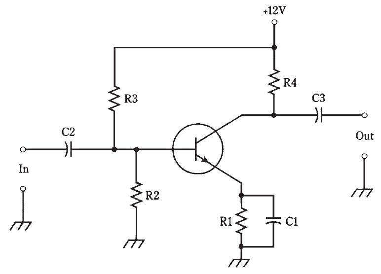
A transistor can be hooked up in three general ways. The emitter can be grounded for signal, the base can be grounded for signal, or the collector can be grounded for signal. Probably the most often-used arrangement is the common-emitter circuit. “Common” means “grounded for the signal.” The basic configuration is shown in Fig. 1.
A terminal can be at ground potential for the signal, and yet have a significant dc voltage. In the circuit shown, C1 looks like a dead short to the ac signal, so the emitter is at signal ground. But R1 causes the emitter to have a certain positive dc voltage with respect to ground (or a negative voltage, if a PNP transistor is used). The exact dc voltage at the emitter depends on the value of R1, and on the bias.

Fig. 1: Common-emitter circuit configuration.
The bias is set by the ratio of resistances R2 and R3. It can be anything from zero, or ground potential, to + 12 V, the supply voltage. Normally it will be a couple of volts. Capacitors C2 and C3 block dc to or from the input and output circuitry (whatever that might be) while letting the ac signal pass. Resistor R4 keeps the output signal from being shorted out through the power supply.
A signal voltage enters the common-emitter circuit through C2, where it causes the base current, IB to vary. The small fluctuations in IB cause large changes in the collector current, IC. This current passes through R4, causing a fluctuating dc voltage to appear across this resistor. The ac part of this passes unhindered through C3 to the output.
The circuit of Fig. 1 is the basis for many amplifiers, from audio frequencies through ultra-high radio frequencies. The common-emitter configuration produces the largest gain of any arrangement. The output is 180 degrees out of phase with the input.
 الاكثر قراءة في الألكترونيات
 اخر الاخبار
اخبار العتبة العباسية المقدسة

الآخبار الصحية


 قسم الشؤون الفكرية يصدر كتاباً يوثق تاريخ السدانة في العتبة العباسية المقدسة
 "المهمة".. إصدار قصصي يوثّق القصص الفائزة في مسابقة فتوى الدفاع المقدسة للقصة القصيرة
 (نوافذ).. إصدار أدبي يوثق القصص الفائزة في مسابقة الإمام العسكري (عليه السلام)


