تاريخ الفيزياء

علماء الفيزياء


الفيزياء الكلاسيكية

الميكانيك

الديناميكا الحرارية


الكهربائية والمغناطيسية

الكهربائية

المغناطيسية

الكهرومغناطيسية


علم البصريات

تاريخ علم البصريات

الضوء

مواضيع عامة في علم البصريات

الصوت


الفيزياء الحديثة


النظرية النسبية

النظرية النسبية الخاصة

النظرية النسبية العامة

مواضيع عامة في النظرية النسبية

ميكانيكا الكم

الفيزياء الذرية

الفيزياء الجزيئية


الفيزياء النووية

مواضيع عامة في الفيزياء النووية

النشاط الاشعاعي


فيزياء الحالة الصلبة

الموصلات

أشباه الموصلات

العوازل

مواضيع عامة في الفيزياء الصلبة

فيزياء الجوامد


الليزر

أنواع الليزر

بعض تطبيقات الليزر

مواضيع عامة في الليزر


علم الفلك

تاريخ وعلماء علم الفلك

الثقوب السوداء


المجموعة الشمسية

الشمس

كوكب عطارد

كوكب الزهرة

كوكب الأرض

كوكب المريخ

كوكب المشتري

كوكب زحل

كوكب أورانوس

كوكب نبتون

كوكب بلوتو

القمر

كواكب ومواضيع اخرى

مواضيع عامة في علم الفلك

النجوم

البلازما

الألكترونيات

خواص المادة


الطاقة البديلة

الطاقة الشمسية

مواضيع عامة في الطاقة البديلة

المد والجزر

فيزياء الجسيمات


الفيزياء والعلوم الأخرى

الفيزياء الكيميائية

الفيزياء الرياضية

الفيزياء الحيوية

الفيزياء العامة


مواضيع عامة في الفيزياء

تجارب فيزيائية

مصطلحات وتعاريف فيزيائية

وحدات القياس الفيزيائية

طرائف الفيزياء

مواضيع اخرى
Coupling methods
المؤلف:
Stan Gibilisco
المصدر:
Teach Yourself Electricity and Electronics
الجزء والصفحة:
449
15-5-2021
2437
Coupling methods
In all of the amplifiers you’ve seen so far, with the exception of the push-pull circuit, capacitors have been used to allow ac to pass while blocking dc. But there is another way to do this, and in some amplifier systems, it is preferred. This is the use of a transformer to couple signals from one stage to the next.
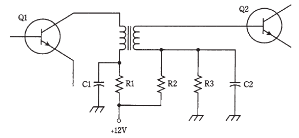
An example of transformer coupling is shown in Fig. 1. Capacitors C1 and C2 keep one end of the transformer primary and secondary at signal ground. Resistor R1 limits the current through the first transistor, Q1. (In some cases, R1 might be eliminated.) Resistors R2 and R3 provide the proper base bias for transistor Q2. The main disadvantage of this scheme is that it costs more than capacitive coupling.
But transformer coupling can provide an optimum signal transfer between amplifier stages with a minimum of loss. This is because of the impedance-matching ability of transformers. Remember that the turns ratio of a transformer affects not only the input and output voltage, but the ratio of impedances. By selecting the right transformer, the output impedance of Q1 can be perfectly matched to the input impedance of Q2.

Fig. 1: Transformer coupling. Component designators and functions are discussed in the text.
In some amplifier systems, capacitors are added across the primary and/or secondary of the transformer. This results in resonance at a frequency determined by the capacitance and the transformer winding inductance. If the set of amplifiers is intended for just one frequency (and this is often the case in RF systems), this method of coupling, called tuned-circuit coupling, enhances the system efficiency. But care must be taken to be sure that the amplifier chain doesn’t get so efficient that it oscillates at the resonant frequency of the tuned circuits!
 الاكثر قراءة في الألكترونيات
 اخر الاخبار
اخبار العتبة العباسية المقدسة

الآخبار الصحية


 قسم الشؤون الفكرية يصدر كتاباً يوثق تاريخ السدانة في العتبة العباسية المقدسة
 "المهمة".. إصدار قصصي يوثّق القصص الفائزة في مسابقة فتوى الدفاع المقدسة للقصة القصيرة
 (نوافذ).. إصدار أدبي يوثق القصص الفائزة في مسابقة الإمام العسكري (عليه السلام)


