The circular polarization
 المؤلف:
Heino Falcke and Friedrich W Hehl
 المصدر:
THE GALACTIC BLACK HOLE Lectures on General Relativity and Astrophysics
 الجزء والصفحة:
p 331
 10-2-2017
 2360
2360
The circular polarization
Finally, to understand the radio properties we also have to consider the surprising results of the polarization observations, where a relatively large circular polarization (CP) was found. The following intuitive explanation is essentially a discussion of CP based on the paper by Beckert and Falcke (2002), where more details can be found. The main point is that linear polarization is naturally obtained in synchrotron radiation (up to 70% for homogeneous magnetic fields), while CP is strongly suppressed in synchrotron plasmas with γe >> 1. The reason

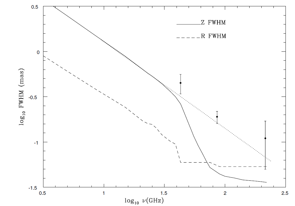
Figure 1.1. Projected size of the major and minor axes of the jet in Sgr A* as a function of frequency. The filled dots mark the size as measured by Lo et al (1998; 43 GHz) and Krichbaum et al (1998; 86 and 215 GHz). The lines represent the predictions of the jet model. At frequencies above 30 GHz one obtains a two component structure with an increasingly stronger core (nozzle, full dashed line) and a fainter jet component (dotted line).
for this is that the narrow beaming cone of the relativistic electrons allows one to see only a small arc along the gyration around the magnetic field. However, CP can be obtained through radiation transfer, particularly through the fact that a magnetic plasma will be naturally birefringent.
For simplicity let us now separate Faraday rotation from conversion and picture only purely linearly or circularly polarized waves in a homogeneous magnetic field.
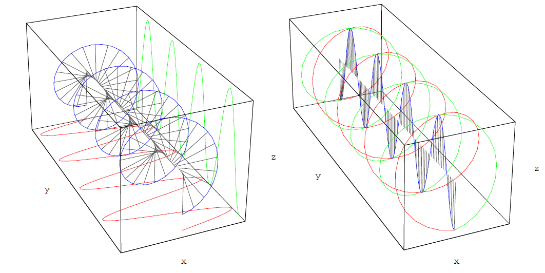
The two orthogonal normal modes for propagation perpendicular to the magnetic field are linearly polarized and a purely circularly polarized wave is split into the two normal modes with a relative phase-shift as shown in figure 1.2 (left). Without a phase-shift the wave will be purely linearly polarized. If, for example, a locally homogeneous magnetic field vertically pervades the box in figure 1.2 (left) along the z-direction, electrons or positrons will be free to move along the field lines and resonate with the vertical mode but hardly resonate with the horizontal mode along the x-direction. This yields the birefringence discussed

Figure 1.2. Left: A circularly polarized wave can be composed of two orthogonal linearly polarized modes shifted in phase. A phase shift would be produced by a plasma in a magnetic field perpendicular to the propagation direction of the waves (here along the z-direction). Without a phase-shift the sum of the two modes would be a purely linearly polarized wave. A video showing the effect of how phase-shifts in a region will turn such a linearly polarized wave into a circularly polarized wave (conversion) A linearly polarized wave can be composed of two orthogonal circularly polarized modes shifted in phase. A phase shift would be produced by a plasma in a magnetic field along the propagation direction of the waves (here along the y-direction). A video showing the effect of additional phase-shifts on the linear polarization, leading to Faraday rotation.
earlier. The resonating electrons or positrons will themselves act as antennas and emit a somewhat delayed wave that interferes with the incoming vertical mode, leading to a slight phase-shift between vertical and horizontal modes. The effect of this shift is shown in the animation, where the resulting wave is circularly polarized and switches from linear to circular polarization as a function of the shift.
Conversion also acts on initially only linearly polarized radiation. The extent of this conversion will depend on the misalignment between the incoming wave and the magnetic field direction since, obviously, a phase-shift between two orthogonal modes will have little effect if one mode is very small or non-existent. Moreover, a random distribution of magnetic field lines on the plane of the sky will reduce circular polarization from conversion in exactly the same way as linear polarization would be reduced.
Analogous to the picture for conversion, one can view a linearly polarized wave as composed of two circularly polarized normal modes when propagating along the magnetic field. This is sketched in figure 1.2 (right), where we will assume a longitudinal magnetic field, i.e. a field along the y-direction. The circular modes will resonate with either electrons or positrons gyrating around the magnetic fields. The latter will again emit a circularly polarized wave, producing a phase shift when interfering with the incoming wave. The effect of the phase shift in the circular modes is shown in an animation of figure 1.2 (right), where one can see that the resulting linearly polarized wave is simply (Faraday) rotated.
An important conclusion to remember, therefore, is that conversion is mainly produced by magnetic field components perpendicular to the line of sight or photon direction, while Faraday rotation is produced by magnetic field components along the line of sight. Moreover, one can also see that conversion is insensitive to the electron/positron ratio while Faraday rotation is not. In figure 1.2 (left) an electron and an positron are both free to move along the z-axis. While they will respond in opposite directions to the incoming wave, their respective emitted waves will also have opposite signs because of opposite charges and hence be identical. In the case of Faraday rotation, the incoming left or right handed circularly polarized wave will only resonate with the particle that also has the correct handedness in its gyration either electron or positron depending on the magnetic field polarity. A pure pair plasma would therefore produce exactly the same phase-shift in left- and right-handed modes and not produce any net Faraday rotation. In the case of excess charge, the direction of Faraday rotation depends on the sign of the excess charge (presumably electrons) and the polarity of the magnetic field. This will indirectly also affect the sign of the circular polarization, if Faraday rotation is the ultimate cause of the misalignment between the plane of polarization and the magnetic field direction.
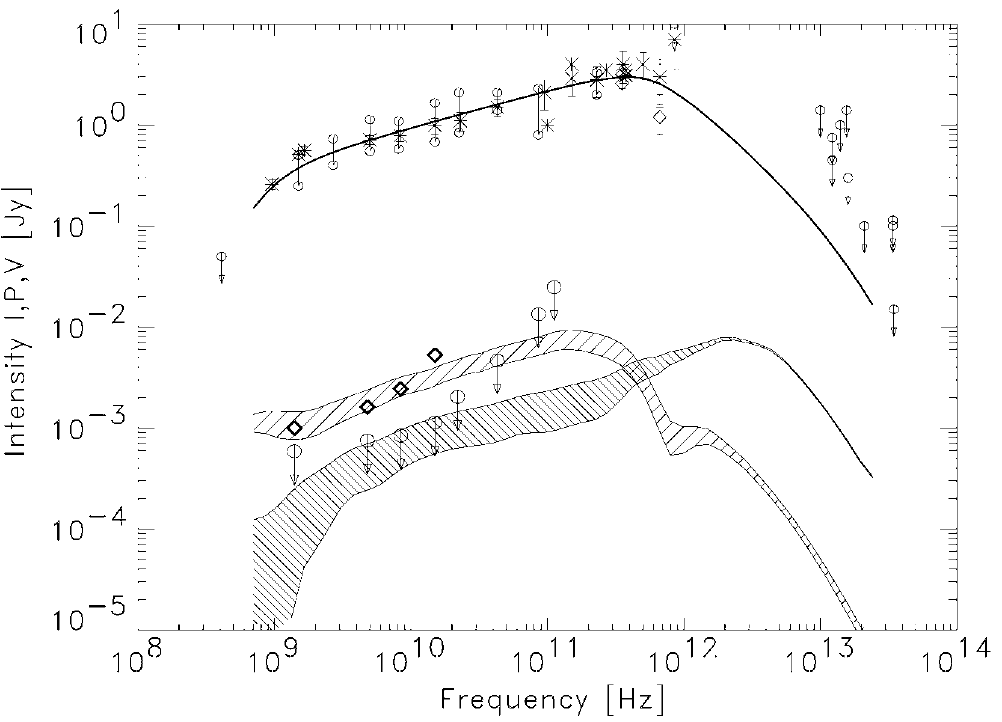
One can include these effects on the polarization into a radiation transfer code and try to reproduce the Sgr A* spectrum and polarization with a jet/out flow model (Beckert and Falcke 2002). The results are shown in figure 1.3 and nicely reproduce the observed spectrum. Two major conclusions can be drawn from this approach:
(i) Since conversion is most effective for low-energy electrons one can conclude that a larger number of these low-energy electrons (1 < γe << 100) are present in Sgr A*. In fact, in the specific modeling mentioned here, one finds that up to a factor of 100 more low energy electrons could be present than the ‘hot’ electrons with γe  100 invoked earlier to explain the spectrum. Hence, a large fraction of Sgr A*'s plasma could reside in a rather inconspicuous, ‘cold’ and non-radiating (hidden) plasma.
(ii) Since the conversion requires an asymmetric magnetic field polarity, an outflow model with a helical magnetic field is strongly favored. The stability of the sign of the CP also suggests that the polarity (the North pole of the black hole/jet) has remained stable over some 20 years a long timescale

Figure 1.3. Outflow model for the radio spectrum of Sgr A* with polarization. The result of model calculations for total flux I (full line), linearly polarized P (dense shaded area), and circularly polarized flux V (sparsely shaded area) are shown for a distance of 8 kpc. Diamonds show the observed circular polarization and circles the observed linear polarization; the rest are observed total flux density values. The numerical calculations are based on the model described in Beckert and Falcke (2002). The shaded areas mark the expected variability due to turbulence. The global magnetic field structure is a spiral with Bφ/Bz = 1.
compared to the accretion time in optically thin accretion flows. It is possible that this stable polarity reflects the stable polarity of the Galactic magnetic field pervading the central parsec of the Galaxy which is accreted onto the black hole.
The main uncertainty in the modeling of the polarization at present reflects the uncertainty in what suppresses the linear polarization in Sgr A*. Here, we have simply assumed that the de-polarization of the linear polarization is due to intrinsic Faraday de-polarization in the radio source itself. However, this could similarly be done in a ‘foreground’ screen, which would most likely be associated with the accretion flow. If that is the case, some of the ‘hidden matter’ mentioned earlier would be in the actual accretion flow and not in the outflow/jet. This can be used to constrain the accretion rate. Estimates by Agol (2000) and Quataert and Gruzinov (2000) then yield a limit on the accretion flow of ˙M < 10−8 to 10−9 Mּ yr−1, given the rotation measures inferred from the linear polarization observations at a λ of 1 mm.
 الاكثر قراءة في الثقوب السوداء
 اخر الاخبار
اخبار العتبة العباسية المقدسة


