تاريخ الفيزياء

علماء الفيزياء


الفيزياء الكلاسيكية

الميكانيك

الديناميكا الحرارية


الكهربائية والمغناطيسية

الكهربائية

المغناطيسية

الكهرومغناطيسية


علم البصريات

تاريخ علم البصريات

الضوء

مواضيع عامة في علم البصريات

الصوت


الفيزياء الحديثة


النظرية النسبية

النظرية النسبية الخاصة

النظرية النسبية العامة

مواضيع عامة في النظرية النسبية

ميكانيكا الكم

الفيزياء الذرية

الفيزياء الجزيئية


الفيزياء النووية

مواضيع عامة في الفيزياء النووية

النشاط الاشعاعي


فيزياء الحالة الصلبة

الموصلات

أشباه الموصلات

العوازل

مواضيع عامة في الفيزياء الصلبة

فيزياء الجوامد


الليزر

أنواع الليزر

بعض تطبيقات الليزر

مواضيع عامة في الليزر


علم الفلك

تاريخ وعلماء علم الفلك

الثقوب السوداء


المجموعة الشمسية

الشمس

كوكب عطارد

كوكب الزهرة

كوكب الأرض

كوكب المريخ

كوكب المشتري

كوكب زحل

كوكب أورانوس

كوكب نبتون

كوكب بلوتو

القمر

كواكب ومواضيع اخرى

مواضيع عامة في علم الفلك

النجوم

البلازما

الألكترونيات

خواص المادة


الطاقة البديلة

الطاقة الشمسية

مواضيع عامة في الطاقة البديلة

المد والجزر

فيزياء الجسيمات


الفيزياء والعلوم الأخرى

الفيزياء الكيميائية

الفيزياء الرياضية

الفيزياء الحيوية

الفيزياء العامة


مواضيع عامة في الفيزياء

تجارب فيزيائية

مصطلحات وتعاريف فيزيائية

وحدات القياس الفيزيائية

طرائف الفيزياء

مواضيع اخرى
Applications of Fermat’s principle
المؤلف:
Richard Feynman, Robert Leighton and Matthew Sands
المصدر:
The Feynman Lectures on Physics
الجزء والصفحة:
Volume I, Chapter 26
2024-03-16
1566
Now let us consider some of the interesting consequences of the principle of least time. First is the principle of reciprocity. If to go from A to B we have found the path of the least time, then to go in the opposite direction (assuming that light goes at the same speed in any direction), the shortest time will be the same path, and therefore, if light can be sent one way, it can be sent the other way.

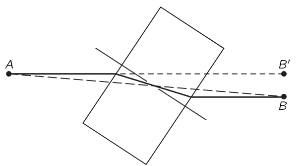
Fig. 26–6. A beam of light is offset as it passes through a transparent block.
An example of interest is a glass block with plane parallel faces, set at an angle to a light beam. Light, in going through the block from a point A to a point B (Fig. 26–6) does not go through in a straight line, but instead it decreases the time in the block by making the angle in the block less inclined, although it loses a little bit in the air. The beam is simply displaced parallel to itself because the angles in and out are the same.

Fig. 26–7. Near the horizon, the apparent sun is higher than the true sun by about 1/2 degree.
A third interesting phenomenon is the fact that when we see the sun setting, it is already below the horizon! It does not look as though it is below the horizon, but it is (Fig. 26–7). The earth’s atmosphere is thin at the top and dense at the bottom. Light travels more slowly in air than it does in a vacuum, and so the light of the sun can get to point S beyond the horizon more quickly if, instead of just going in a straight line, it avoids the dense regions where it goes slowly by getting through them at a steeper tilt. When it appears to go below the horizon, it is actually already well below the horizon. Another example of this phenomenon is the mirage that one often sees while driving on hot roads. One sees “water” on the road, but when he gets there, it is as dry as the desert! The phenomenon is the following. What we are really seeing is the sky light “reflected” on the road: light from the sky, heading for the road, can end up in the eye, as shown in Fig. 26–8. Why? The air is very hot just above the road but it is cooler up higher. Hotter air is more expanded than cooler air and is thinner, and this decreases the speed of light less. That is to say, light goes faster in the hot region than in the cool region. Therefore, instead of the light deciding to come in the straightforward way, it also has a least-time path by which it goes into the region where it goes faster for a while, in order to save time. So, it can go in a curve.

Fig. 26–8. A mirage.
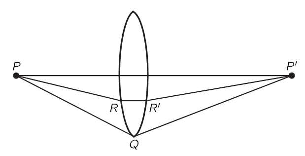
As another important example of the principle of least time, suppose that we would like to arrange a situation where we have all the light that comes out of one point, P, collected back together at another point, P′ (Fig. 26–9). That means, of course, that the light can go in a straight line from P to P′. That is all right. But how can we arrange that not only does it go straight, but also so that the light starting out from P toward Q also ends up at P′? We want to bring all the light back to what we call a focus. How? If the light always takes the path of least time, then certainly it should not want to go over all these other paths. The only way that the light can be perfectly satisfied to take several adjacent paths is to make those times exactly equal! Otherwise, it would select the one of least time. Therefore, the problem of making a focusing system is merely to arrange a device so that it takes the same time for the light to go on all the different paths!

Fig. 26–9. An optical “black box.”
This is easy to do. Suppose that we had a piece of glass in which light goes slower than it does in the air (Fig. 26–10). Now consider a ray which goes in air in the path PQP′. That is a longer path than from P directly to P′ and no doubt takes a longer time. But if we were to insert a piece of glass of just the right thickness (we shall later figure out how thick) it might exactly compensate the excess time that it would take the light to go at an angle! In those circumstances we can arrange that the time the light takes to go straight through is the same as the time it takes to go in the path PQP′. Likewise, if we take a ray PRR′P′ which is partly inclined, it is not quite as long as PQP′, and we do not have to compensate as much as for the straight one, but we do have to compensate somewhat. We end up with a piece of glass that looks like Fig. 26–10. With this shape, all the light which comes from P will go to P′. This, of course, is well known to us, and we call such a device a converging lens. In the next chapter we shall actually calculate what shape the lens has to have to make a perfect focus.

Fig. 26–10.A focusing optical system.
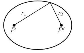
Take another example: suppose we wish to arrange some mirrors so that the light from P always goes to P′ (Fig. 26–11). On any path, it goes to some mirror and comes back, and all times must be equal. Here the light always travels in air, so the time and the distance are proportional. Therefore, the statement that all the times are the same is the same as the statement that the total distance is the same. Thus, the sum of the two distances r1 and r2 must be a constant. An ellipse is that curve which has the property that the sum of the distances from two points is a constant for every point on the ellipse; thus we can be sure that the light from one focus will come to the other.

Fig. 26–11. An ellipsoidal mirror.
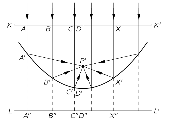
The same principle works for gathering the light of a star. The great 200-inch Palomar telescope is built on the following principle. Imagine a star billions of miles away; we would like to cause all the light that comes in to come to a focus. Of course, we cannot draw the rays that go all the way up to the star, but we still want to check whether the times are equal. Of course, we know that when the various rays have arrived at some plane KK′, perpendicular to the rays, all the times in this plane are equal (Fig. 26–12). The rays must then come down to the mirror and proceed toward P′ in equal times. That is, we must find a curve which has the property that the sum of the distances XX′+X′P′ is a constant, no matter where X is chosen. An easy way to find it is to extend the length of the line XX′ down to a plane LL′. Now if we arrange our curve so that A′A′′=A′P′, B′B′′=B′P′, C′C′′=C′P′, and so on, we will have our curve, because then of course, AA′+A′P′=AA′+A′A′′ will be constant. Thus our curve is the locus of all points equidistant from a line and a point. Such a curve is called a parabola; the mirror is made in the shape of a parabola.

Fig. 26–12.A paraboloidal mirror.
The above examples illustrate the principle upon which such optical devices can be designed. The exact curves can be calculated using the principle that, to focus perfectly, the travel times must be exactly equal for all light rays, as well as being less than for any other nearby path.
We shall discuss these focusing optical devices further in the next chapter; let us now discuss the further development of the theory. When a new theoretical principle is developed, such as the principle of least time, our first inclination might be to say, “Well, that is very pretty; it is delightful; but the question is, does it help at all in understanding the physics?” Someone may say, “Yes, look at how many things we can now understand!” Another says, “Very well, but I can understand mirrors, too. I need a curve such that every tangent plane makes equal angles with the two rays. I can figure out a lens, too, because every ray that comes to it is bent through an angle given by Snell’s law.” Evidently the statement of least time and the statement that angles are equal on reflection, and that the sines of the angles are proportional on refraction, are the same. So is it merely a philosophical question, or one of beauty? There can be arguments on both sides.
However, the importance of a powerful principle is that it predicts new things.
It is easy to show that there are a number of new things predicted by Fermat’s principle. First, suppose that there are three media, glass, water, and air, and we perform a refraction experiment and measure the index n for one medium against another. Let us call n12 the index of air (1) against water (2); n13 the index of air (1) against glass (3). If we measured water against glass, we should find another index, which we shall call n23. But there is no a priori reason why there should be any connection between n12, n13, and n23. On the other hand, according to the idea of least time, there is a definite relationship. The index n12 is the ratio of two things, the speed in air to the speed in water; n13 is the ratio of the speed in air to the speed in glass; n23 is the ratio of the speed in water to the speed in glass. Therefore, we cancel out the air, and get

In other words, we predict that the index for a new pair of materials can be obtained from the indexes of the individual materials, both against air or against vacuum. So if we measure the speed of light in all materials, and from this get a single number for each material, namely its index relative to vacuum, called ni (n1 is the speed in vacuum relative to the speed in air, etc.), then our formula is easy. The index for any two materials i and j is

Using only Snell’s law, there is no basis for a prediction of this kind.1 But of course this prediction works. The relation (26.5) was known very early, and was a very strong argument for the principle of least time.
Another argument for the principle of least time, another prediction, is that if we measure the speed of light in water, it will be lower than in air. This is a prediction of a completely different type. It is a brilliant prediction, because all we have so far measured are angles; here we have a theoretical prediction which is quite different from the observations from which Fermat deduced the idea of least time. It turns out, in fact, that the speed in water is slower than the speed in air, by just the proportion that is needed to get the right index!
 الاكثر قراءة في مواضيع عامة في علم البصريات
 اخر الاخبار
اخبار العتبة العباسية المقدسة

الآخبار الصحية


 قسم الشؤون الفكرية يصدر كتاباً يوثق تاريخ السدانة في العتبة العباسية المقدسة
 "المهمة".. إصدار قصصي يوثّق القصص الفائزة في مسابقة فتوى الدفاع المقدسة للقصة القصيرة
 (نوافذ).. إصدار أدبي يوثق القصص الفائزة في مسابقة الإمام العسكري (عليه السلام)


