Next let us discuss the mathematics involved in combining the effects of two oscillators to find the net field at a given point. This is very easy in the few cases that we considered in the previous chapter. We shall first describe the effects qualitatively, and then more quantitatively. Let us take the simple case, where the oscillators are situated with their centers in the same horizontal plane as the detector, and the line of vibration is vertical.

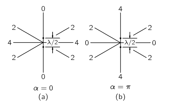
Fig. 29–5. The intensities in various directions from two dipole oscillators one-half wavelength apart. Left: in phase (α=0). Right: one-half period out of phase (α=π).
Figure 29–5 (a) represents the top view of two such oscillators, and in this particular example they are half a wavelength apart in a N–S direction, and are oscillating together in the same phase, which we call zero phase. Now we would like to know the intensity of the radiation in various directions. By the intensity we mean the amount of energy that the field carries past us per second, which is proportional to the square of the field, averaged in time. So, the thing to look at, when we want to know how bright the light is, is the square of the electric field, not the electric field itself. (The electric field tells the strength of the force felt by a stationary charge, but the amount of energy that is going past, in watts per square meter, is proportional to the square of the electric field. We shall derive the constant of proportionality in Chapter 31.) If we look at the array from the W side, both oscillators contribute equally and in phase, so the electric field is twice as strong as it would be from a single oscillator. Therefore, the intensity is four times as strong as it would be if there were only one oscillator. (The numbers in Fig. 29–5 represent how strong the intensity would be in this case, compared with what it would be if there were only a single oscillator of unit strength.) Now, in either the N or S direction along the line of the oscillators, since they are half a wavelength apart, the effect of one oscillator turns out to be out of phase by exactly half an oscillation from the other, and therefore the fields add to zero. At a certain particular intermediate angle (in fact, at 30∘) the intensity is 2, and it falls off, 4, 2, 0, and so forth. We have to learn how to find these numbers at other angles. It is a question of adding two oscillations with different phases.
Let us quickly look at some other cases of interest. Suppose the oscillators are again one-half a wavelength apart, but the phase α of one is set half a period behind the other in its oscillation (Fig. 29–5b). In the W direction the intensity is now zero, because one oscillator is “pushing” when the other one is “pulling.” But in the N direction the signal from the near one comes at a certain time, and that of the other comes half a period later. But the latter was originally half a period behind in timing, and therefore it is now exactly in time with the first one, and so the intensity in this direction is 4 units. The intensity in the direction at 30∘ is still 2, as we can prove later.
Now we come to an interesting case which shows up a possibly useful feature. Let us remark that one of the reasons that phase relations of oscillators are interesting is for beaming radio transmitters. For instance, if we build an antenna system and want to send a radio signal, say, to Hawaii, we set the antennas up as in Fig. 29–5(a) and we broadcast with our two antennas in phase, because Hawaii is to the west of us. Then we decide that tomorrow we are going to broadcast toward Alberta, Canada. Since that is north, not west, all we have to do is to reverse the phase of one of our antennas, and we can broadcast to the north. So, we can build antenna systems with various arrangements. Ours is one of the simplest possible ones; we can make them much more complicated, and by changing the phases in the various antennas we can send the beams in various directions and send most of the power in the direction in which we wish to transmit, without ever moving the antenna! In both of the preceding cases, however, while we are broadcasting toward Alberta, we are wasting a lot of power on Easter Island, and it would be interesting to ask whether it is possible to send it in only one direction. At first sight we might think that with a pair of antennas of this nature the result is always going to be symmetrical. So let us consider a case that comes out unsymmetrical, to show the possible variety.

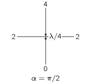
Fig. 29–6. A pair of dipole antennas giving maximum power in one direction.
If the antennas are separated by one-quarter wavelength, and if the N one is one-fourth period behind the S one in time, then what happens (Fig. 29–6)? In the W direction we get 2, as we will see later. In the S direction we get zero, because the signal from S comes at a certain time; that from N comes 90∘ later in time, but it is already 90∘ behind in its built-in phase, therefore it arrives, altogether, 180∘ out of phase, and there is no effect. On the other hand, in the N direction, the N signal arrives earlier than the S signal by 90∘ in time, because it is a quarter wavelength closer. But its phase is set so that it is oscillating 90∘ behind in time, which just compensates the delay difference, and therefore the two signals appear together in phase, making the field strength twice as large, and the energy four times as great.
Thus, by using some cleverness in spacing and phasing our antennas, we can send the power all in one direction. But still it is distributed over a great range of angles. Can we arrange it so that it is focused still more sharply in a particular direction? Let us consider the case of Hawaii again, where we are sending the beam east and west but it is spread over quite an angle, because even at 30∘ we are still getting half the intensity—we are wasting the power. Can we do better than that? Let us take a situation in which the separation is ten wavelengths (Fig. 29–7), which is more nearly comparable to the situation in which we experimented in the previous chapter, with separations of several wavelengths rather than a small fraction of a wavelength. Here the picture is quite different.

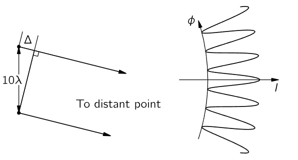
Fig. 29–7. The intensity pattern for two dipoles separated by 10λ.
If the oscillators are ten wavelengths apart (we take the in-phase case to make it easy), we see that in the E–W direction, they are in phase, and we get a strong intensity, four times what we would get if one of them were there alone. On the other hand, at a very small angle away, the arrival times differ by 180∘ and the intensity is zero. To be precise, if we draw a line from each oscillator to a distant point and the difference Δ in the two distances is λ/2, half an oscillation, then they will be out of phase. So this first null occurs when that happens. (The figure is not drawn to scale; it is only a rough sketch.) This means that we do indeed have a very sharp beam in the direction we want, because if we just move over a little bit we lose all our intensity. Unfortunately for practical purposes, if we were thinking of making a radio broadcasting array and we doubled the distance Δ, then we would be a whole cycle out of phase, which is the same as being exactly in phase again! Thus, we get many successive maxima and minima, just as we found with the 212λ.
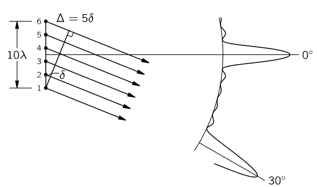
Now how can we arrange to get rid of all these extra maxima, or “lobes,” as they are called? We could get rid of the unwanted lobes in a rather interesting way. Suppose that we were to place another set of antennas between the two that we already have. That is, the outside ones are still 10λ apart, but between them, say every 2λ, we have put another antenna, and we drive them all in phase. There are now six antennas, and if we looked at the intensity in the E–W direction, it would, of course, be much higher with six antennas than with one. The field would be six times and the intensity thirty-six times as great (the square of the field). We get 36 units of intensity in that direction. Now if we look at neighboring points, we find a zero as before, roughly, but if we go farther, to where we used to get a big “bump,” we get a much smaller “bump” now. Let us try to see why.

Fig. 29–8. A six-dipole antenna array and part of its intensity pattern.
The reason is that although we might expect to get a big bump when the distance Δ is exactly equal to the wavelength, it is true that dipoles 1 and 6 are then in phase and are cooperating in trying to get some strength in that direction. But numbers 3 and 4 are roughly 12 a wavelength out of phase with 1 and 6, and although 1 and 6 push together, 3 and 4 push together too, but in opposite phase. Therefore, there is very little intensity in this direction—but there is something; it does not balance exactly. This kind of thing keeps on happening; we get very little bumps, and we have the strong beam in the direction where we want it. But in this particular example, something else will happen: namely, since the distance between successive dipoles is 2λ, it is possible to find an angle where the distance δ between successive dipoles is exactly one wavelength, so that the effects from all of them are in phase again. Each one is delayed relative to the next one by 360∘, so they all come back in phase, and we have another strong beam in that direction! It is easy to avoid this in practice because it is possible to put the dipoles closer than one wavelength apart. If we put in more antennas, closer than one wavelength apart, then this cannot happen. But the fact that this can happen at certain angles, if the spacing is bigger than one wavelength, is a very interesting and useful phenomenon in other applications—not radio broadcasting, but in diffraction gratings.
 الاكثر قراءة في مواضيع عامة في علم البصريات
 اخر الاخبار
اخبار العتبة العباسية المقدسة


