


 الفيزياء الكلاسيكية
 الكهربائية والمغناطيسية
 علم البصريات
 الفيزياء الحديثة
 النظرية النسبية
 الفيزياء النووية
 فيزياء الحالة الصلبة
 الليزر
 علم الفلك
 المجموعة الشمسية
 الطاقة البديلة
 الفيزياء والعلوم الأخرى
 مواضيع عامة في الفيزياء
|
أقرأ أيضاً
التاريخ: 28-12-2019
التاريخ: 4-1-2021
التاريخ: 2024-04-06
التاريخ: 2024-03-20
|
Now we have finished our analysis of the phenomena of dipole radiators qualitatively, and we must learn how to analyze them quantitatively. To find the effect of two sources at some particular angle in the most general case, where the two oscillators have some intrinsic relative phase α from one another and the strengths A1 and A2 are not equal, we find that we have to add two cosines having the same frequency, but with different phases. It is very easy to find this phase difference; it is made up of a delay due to the difference in distance, and the intrinsic, built-in phase of the oscillation. Mathematically, we have to find the sum R of two waves: R=A1cos(ωt+ϕ1)+A2cos(ωt+ϕ2). How do we do it?
It is really very easy, and we presume that we already know how to do it. However, we shall outline the procedure in some detail. First, we can, if we are clever with mathematics and know enough about cosines and sines, simply work it out. The easiest such case is the one where A1 and A2 are equal, let us say they are both equal to A. In those circumstances, for example (we could call this the trigonometric method of solving the problem), we have
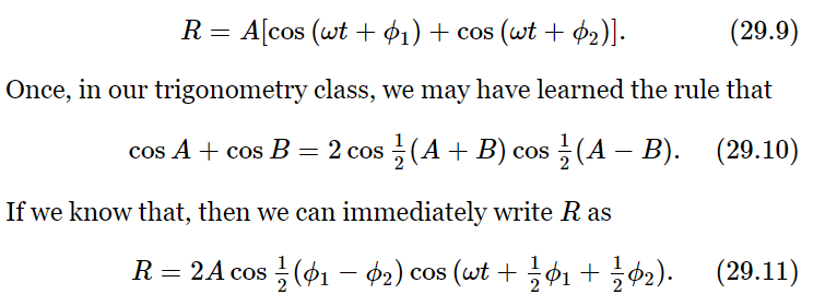
So we find that we have an oscillatory wave with a new phase and a new amplitude. In general, the result will be an oscillatory wave with a new amplitude AR, which we may call the resultant amplitude, oscillating at the same frequency but with a phase difference ϕR, called the resultant phase. In view of this, our particular case has the following result: that the resultant amplitude is

and the resultant phase is the average of the two phases, and we have completely solved our problem.
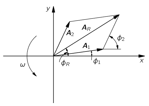
Fig. 29–9. A geometrical method for combining two cosine waves. The entire diagram is thought of as rotating counterclockwise with angular frequency ω.
Now suppose that we cannot remember that the sum of two cosines is twice the cosine of half the sum times the cosine of half the difference. Then we may use another method of analysis which is more geometrical. Any cosine function of ωt can be considered as the horizontal projection of a rotating vector. Suppose there were a vector A1 of length A1 rotating with time, so that its angle with the horizontal axis is ωt+ϕ1. (We shall leave out the ωt in a minute, and see that it makes no difference.) Suppose that we take a snapshot at the time t=0, although, in fact, the picture is rotating with angular velocity ω (Fig. 29–9). The projection of A1 along the horizontal axis is precisely A1cos(ωt+ϕ1). Now at t=0 the second wave could be represented by another vector, A2, of length A2 and at an angle ϕ2, and also rotating. They are both rotating with the same angular velocity ω, and therefore the relative positions of the two are fixed. The system goes around like a rigid body. The horizontal projection of A2 is A2cos(ωt+ϕ2). But we know from the theory of vectors that if we add the two vectors in the ordinary way, by the parallelogram rule, and draw the resultant vector AR, the x-component of the resultant is the sum of the x-components of the other two vectors. That solves our problem. It is easy to check that this gives the correct result for the special case we treated above, where A1= A2= A. In this case, we see from Fig. 29–9 that AR lies midway between A1 and A2 and makes an angle 1/2 (ϕ2−ϕ1) with each. Therefore, we see that AR=2A cos 1/2 (ϕ2−ϕ1), as before. Also, as we see from the triangle, the phase of AR, as it goes around, is the average angle of A1 and A2 when the two amplitudes are equal. Clearly, we can also solve for the case where the amplitudes are not equal, just as easily. We can call that the geometrical way of solving the problem.
There is still another way of solving the problem, and that is the analytical way. That is, instead of having actually to draw a picture like Fig. 29–9, we can write something down which says the same thing as the picture: instead of drawing the vectors, we write a complex number to represent each of the vectors. The real parts of the complex numbers are the actual physical quantities. So, in our particular case the waves could be written in this way: A1ei(ωt+ϕ1) [the real part of this is A1cos(ωt+ϕ1)] and A2ei(ωt+ϕ2). Now we can add the two:

This solves the problem that we wanted to solve, because it represents the result as a complex number of magnitude AR and phase ϕR.
To see how this method works, let us find the amplitude AR which is the “length” of  To get the “length” of a complex quantity, we always multiply the quantity by its complex conjugate, which gives the length squared. The complex conjugate is the same expression, but with the sign of the i’s reversed. Thus, we have
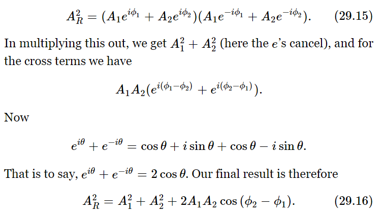
As we see, this agrees with the length of AR in Fig. 29–9, using the rules of trigonometry.
Thus, the sum of the two effects has the intensity A21 we would get with one of them alone, plus the intensity A22 we would get with the other one alone, plus a correction. This correction we call the interference effect. It is really only the difference between what we get simply by adding the intensities, and what actually happens. We call it interference whether it is positive or negative. (Interference in ordinary language usually suggests opposition or hindrance, but in physics we often do not use language the way it was originally designed!) If the interference term is positive, we call that case constructive interference, horrible though it may sound to anybody other than a physicist! The opposite case is called destructive interference.
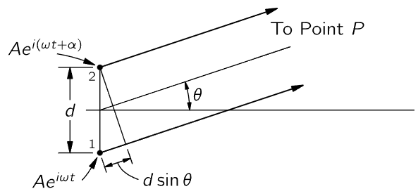
Fig. 29–10. Two oscillators of equal amplitude, with a phase difference α between them.
Now let us see how to apply our general formula (29.16) for the case of two oscillators to the special situations which we have discussed qualitatively. To apply this general formula, it is only necessary to find what phase difference, ϕ2−ϕ1, exists between the signals arriving at a given point. (It depends only on the phase difference, of course, and not on the phase itself.) So let us consider the case where the two oscillators, of equal amplitude, are separated by some distance d and have an intrinsic relative phase α. (When one is at phase zero, the phase of the other is α.) Then we ask what the intensity will be in some azimuth direction θ from the E–W line. [Note that this is not the same θ as appears in (29.1). We are torn between using an unconventional symbol like U, or the conventional symbol θ (Fig. 29–10).] The phase relationship is found by noting that the difference in distance from P to the two oscillators is d sinθ, so that the phase difference contribution from this is the number of wavelengths in d sinθ, multiplied by 2π. (Those who are more sophisticated might want to multiply the wave number k, which is the rate of change of phase with distance, by d sinθ; it is exactly the same.) The phase difference due to the distance difference is thus 2πd sinθ/λ, but, due to the timing of the oscillators, there is an additional phase α. So the phase difference at arrival would be

This takes care of all the cases. Thus, all we have to do is substitute this expression into (29.16) for the case A1=A2, and we can calculate all the various results for two antennas of equal intensity.
Now let us see what happens in our various cases. The reason we know, for example, that the intensity is 2 at 30∘ in Fig. 29–5 is the following: the two oscillators are 1/2 λ apart, so at 30∘, d sinθ=λ/4. Thus ϕ2−ϕ1= 2πλ/4λ= π/2, and so the interference term is zero. (We are adding two vectors at 90∘.) The result is the hypotenuse of a 45∘ right-angle triangle, which is √2 times the unit amplitude; squaring it, we get twice the intensity of one oscillator alone. All the other cases can be worked out in this same way.


|
|
|
|
دراسة تحدد أفضل 4 وجبات صحية.. وأخطرها
|
|
|
|
|
|
|
جامعة الكفيل تحتفي بذكرى ولادة الإمام محمد الجواد (عليه السلام)
|
|
|