تاريخ الفيزياء

علماء الفيزياء


الفيزياء الكلاسيكية

الميكانيك

الديناميكا الحرارية


الكهربائية والمغناطيسية

الكهربائية

المغناطيسية

الكهرومغناطيسية


علم البصريات

تاريخ علم البصريات

الضوء

مواضيع عامة في علم البصريات

الصوت


الفيزياء الحديثة


النظرية النسبية

النظرية النسبية الخاصة

النظرية النسبية العامة

مواضيع عامة في النظرية النسبية

ميكانيكا الكم

الفيزياء الذرية

الفيزياء الجزيئية


الفيزياء النووية

مواضيع عامة في الفيزياء النووية

النشاط الاشعاعي


فيزياء الحالة الصلبة

الموصلات

أشباه الموصلات

العوازل

مواضيع عامة في الفيزياء الصلبة

فيزياء الجوامد


الليزر

أنواع الليزر

بعض تطبيقات الليزر

مواضيع عامة في الليزر


علم الفلك

تاريخ وعلماء علم الفلك

الثقوب السوداء


المجموعة الشمسية

الشمس

كوكب عطارد

كوكب الزهرة

كوكب الأرض

كوكب المريخ

كوكب المشتري

كوكب زحل

كوكب أورانوس

كوكب نبتون

كوكب بلوتو

القمر

كواكب ومواضيع اخرى

مواضيع عامة في علم الفلك

النجوم

البلازما

الألكترونيات

خواص المادة


الطاقة البديلة

الطاقة الشمسية

مواضيع عامة في الطاقة البديلة

المد والجزر

فيزياء الجسيمات


الفيزياء والعلوم الأخرى

الفيزياء الكيميائية

الفيزياء الرياضية

الفيزياء الحيوية

الفيزياء العامة


مواضيع عامة في الفيزياء

تجارب فيزيائية

مصطلحات وتعاريف فيزيائية

وحدات القياس الفيزيائية

طرائف الفيزياء

مواضيع اخرى
SINGLE-FREQUENCY OPERATION
المؤلف:
Mark Csele
المصدر:
FUNDAMENTALS OF LIGHT SOURCES AND LASERS
الجزء والصفحة:
p169
17-3-2016
3902
SINGLE-FREQUENCY OPERATION
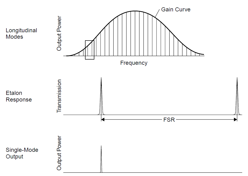
Consider an argon laser that has a relatively large bandwidth, allowing a large number of longitudinal modes (with slightly different frequencies) to oscillate simultaneously

Figure 1.1. Longitudinal modes and gain profile in a laser.
as in Figure 1.1, in which a small section of the output is expanded to show details of each individual mode. We discovered that the gain bandwidth of the argon laser (broadened primarily by Doppler effects) is about 5 GHz. Inside this 5-GHz range there are many longitudinal modes: The 90- cm laser used in the example had modes spaced 167 MHz apart, for a total of 30 modes. If an etalon (basically, a compact interferometer) is designed such that it is resonant only at wavelengths spaced farther apart than 5 GHz, the laser can be made to operate on a single mode (and hence a single frequency). The spacing of the resonant peaks of an etalon, called the free spectral range (FSR) of an etalon, is evident in the middle diagram in Figure 1.2. Only when a resonant peak of the etalon and a longitudinal mode of the laser have the same frequency will the laser have enough gain to oscillate.

Figure 1.2. Selection of a single mode with an etalon.

A practical etalon consists of a glass slide (usually quartz, to reduce absorption) coated on either side with a slightly reflective thin-film coating. The etalon acts as an interferometer which is resonant only at certain wavelengths. It is inserted inside the cavity of a laser, which has a wavelength selector in the cavity so that only a single line oscillates, as in Figure 1.3. A wavelength selector is required for a multiline laser such as an argon-ion laser, but where the laser optics themselves are resonant at only a single wavelength (as is frequently the case with helium–neon lasers optimized for the red wavelength), the wavelength selector is unnecessary.
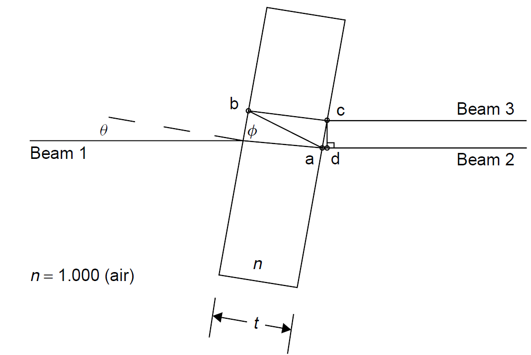
The etalon is always tilted with respect to the optical axis of the laser were it not, it would act as a simple mirror, which would not select wavelength. An examination of the optical path inside the etalon provided in Figure 1.4 reveals that an incoming beam (beam 1) enters the etalon and is refracted. It refracts again upon exit and leaves the etalon as beam 2, but a portion of the beam (about 20% for a typical etalon used with a low-gain gas laser) is reflected from the coating on the side of the etalon and is reflected back into the etalon along path a–b. The beam is reflected again, becoming b–c, and is refracted upon exit, becoming beam 3. If the difference in path length between beams 2 and 3 is an integral number of wavelengths, constructive interference occurs and the transmission of the etalon is seen as nearly

Figure 1.4. Optical path inside an etalon.
100%. Conversely, when the paths are not separated by an exact number of wavelengths, beam 3 exits the etalon with a phase different from that of beam 2. Destructive interference occurs in this case, and the transmission is seen as low for the filter.
Mathematically, we can express the condition for constructive interference (i.e., maximum transmission) as the point where the path length for beam 3 is an integer number:
Nλ = n(distance a–b distance b–c) distance a–d (1.1)
where N is an integer. Geometrically, we can express this (the condition for exit beams to all be in phase) as a function of the angle at which incident light is refracted in the etalon:
Nλ = 2nt cos ϕ (1.2)
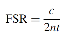
This is, of course, the familiar formula used to describe the Fabry Perot interferometer. Small-angle approximations can be applied (for a standard application in which the etalon is just barely tilted in the laser cavity). In this case we can approximate ϕ with θ/n. Finally, the spacing of resonant peaks (the FSR) of this etalon is found to be
 (1.3)
(1.3)
This is the same result as that developed earlier for the longitudinal modes of a laser cavity. For an etalon made of quartz with a thickness of 10 mm, the FSR is 10.3 GHz, well suited for use in the argon laser above, where the gain bandwidth is 5 GHz (i.e., it would be impossible for two longitudinal modes to overlap and oscillate simultaneously). Note that the faces of the etalon must be very flat and parallel and that thicker etalons will have smaller FSR spacing (which must be chosen accordingly to ensure that FSR is larger than the gain bandwidth).
Equation (1.2) indicates that tuning of the etalon can be accomplished by changing the angle of the device with respect to the optical axis of the laser. Although this seems reasonable, one must be cautious, since the interfering beams (beams 2 and 3 in the figure) will separate (distance c–d increases) as the etalon is tilted, resulting in what is termed walk-off loss. This complication usually prevents angle tuning of an etalon in a low-gain laser, but an alternative method (the one generally used with etalons of this type) is temperature tuning. Consider that for essentially all materials, the index of refraction depends on the ambient temperature. In the case of quartz, n will vary by about 1 × 10⁻⁵ per degree C. This corresponds to a frequency change of about 5 GHz per degree C of temperature change. By controlling the temperature carefully, one can select any one longitudinal mode within the gain bandwidth of the laser. Obviously, extremely accurate temperature control of the etalon is required for stability (usually, about 0.01 degree C) and the etalon is enclosed in an oven.

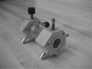
Figure 1.5. Air-spaced etalon.
Finally, etalons may be constructed using air (or another gas) as a spacer, as shown in Figure 1.5. In this etalon two partially reflective optical windows are separated by a mechanical mount designed to keep them perfectly aligned (the two knobs protruding from the device allow alignment of the optics). The entire etalon may be tuned by either changing the angle of the entire etalon in the cavity or changing the gas and gas pressure within the device, which affects the index of refraction. The latter is usually preferred, to prevent walk-off losses. In the case of this particular etalon (which is used with an ion laser), the spacing between the optics is 10 cm, so the FSR is calculated to be 15 GHz when air is used. As we had calculated earlier, the linewidth of a single longitudinal mode is predicted to be (for a 488-nm argon laser) under 1 MHz.
Narrow spectral widths result in long coherence lengths, coherence length being the distance over which the phases of multiple wavelengths (longitudinal modes) in the output beam stay reasonably in phase with each other. If the output beam consists of many longitudinal modes (each at slightly different frequencies), they will interfere destructively at some point, destroying the coherence of the beam. If, on the other hand, the output beam consists of a single extremely narrow (in frequency spread) mode, the beam will stay coherent for a great distance. Coherence length is hence related to spectral width: The wider the spectral width, the shorter the coherence length. It is defined (in units of meters) as
 (1.4)
(1.4)
where Δv is the spectral width in hertz.
Example 1.1 Spectral Width versus Coherence Length Consider the spectral width of a regular and a single-frequency He Ne laser. We calculated the spectral width of a He Ne laser to be 1.56 GHz and so:

By selecting a single mode (with a spectral width of about 1 MHz), the coherence length increases to 300 m! For a laser with a larger inherent spectral width, such as an argon laser, single-frequency operation is quite desirable to allow this laser to be used as a source in making holograms (where a spectrally narrow source leads to better depth in the recorded image).
 الاكثر قراءة في مواضيع عامة في علم البصريات
 اخر الاخبار
اخبار العتبة العباسية المقدسة

الآخبار الصحية


 قسم الشؤون الفكرية يصدر كتاباً يوثق تاريخ السدانة في العتبة العباسية المقدسة
 "المهمة".. إصدار قصصي يوثّق القصص الفائزة في مسابقة فتوى الدفاع المقدسة للقصة القصيرة
 (نوافذ).. إصدار أدبي يوثق القصص الفائزة في مسابقة الإمام العسكري (عليه السلام)


