تاريخ الفيزياء

علماء الفيزياء


الفيزياء الكلاسيكية

الميكانيك

الديناميكا الحرارية


الكهربائية والمغناطيسية

الكهربائية

المغناطيسية

الكهرومغناطيسية


علم البصريات

تاريخ علم البصريات

الضوء

مواضيع عامة في علم البصريات

الصوت


الفيزياء الحديثة


النظرية النسبية

النظرية النسبية الخاصة

النظرية النسبية العامة

مواضيع عامة في النظرية النسبية

ميكانيكا الكم

الفيزياء الذرية

الفيزياء الجزيئية


الفيزياء النووية

مواضيع عامة في الفيزياء النووية

النشاط الاشعاعي


فيزياء الحالة الصلبة

الموصلات

أشباه الموصلات

العوازل

مواضيع عامة في الفيزياء الصلبة

فيزياء الجوامد


الليزر

أنواع الليزر

بعض تطبيقات الليزر

مواضيع عامة في الليزر


علم الفلك

تاريخ وعلماء علم الفلك

الثقوب السوداء


المجموعة الشمسية

الشمس

كوكب عطارد

كوكب الزهرة

كوكب الأرض

كوكب المريخ

كوكب المشتري

كوكب زحل

كوكب أورانوس

كوكب نبتون

كوكب بلوتو

القمر

كواكب ومواضيع اخرى

مواضيع عامة في علم الفلك

النجوم

البلازما

الألكترونيات

خواص المادة


الطاقة البديلة

الطاقة الشمسية

مواضيع عامة في الطاقة البديلة

المد والجزر

فيزياء الجسيمات


الفيزياء والعلوم الأخرى

الفيزياء الكيميائية

الفيزياء الرياضية

الفيزياء الحيوية

الفيزياء العامة


مواضيع عامة في الفيزياء

تجارب فيزيائية

مصطلحات وتعاريف فيزيائية

وحدات القياس الفيزيائية

طرائف الفيزياء

مواضيع اخرى
HeNe POWER SUPPLIES
المؤلف:
Mark Csele
المصدر:
FUNDAMENTALS OF LIGHT SOURCES AND LASERS
الجزء والصفحة:
p241
22-3-2016
2793
HeNe POWER SUPPLIES
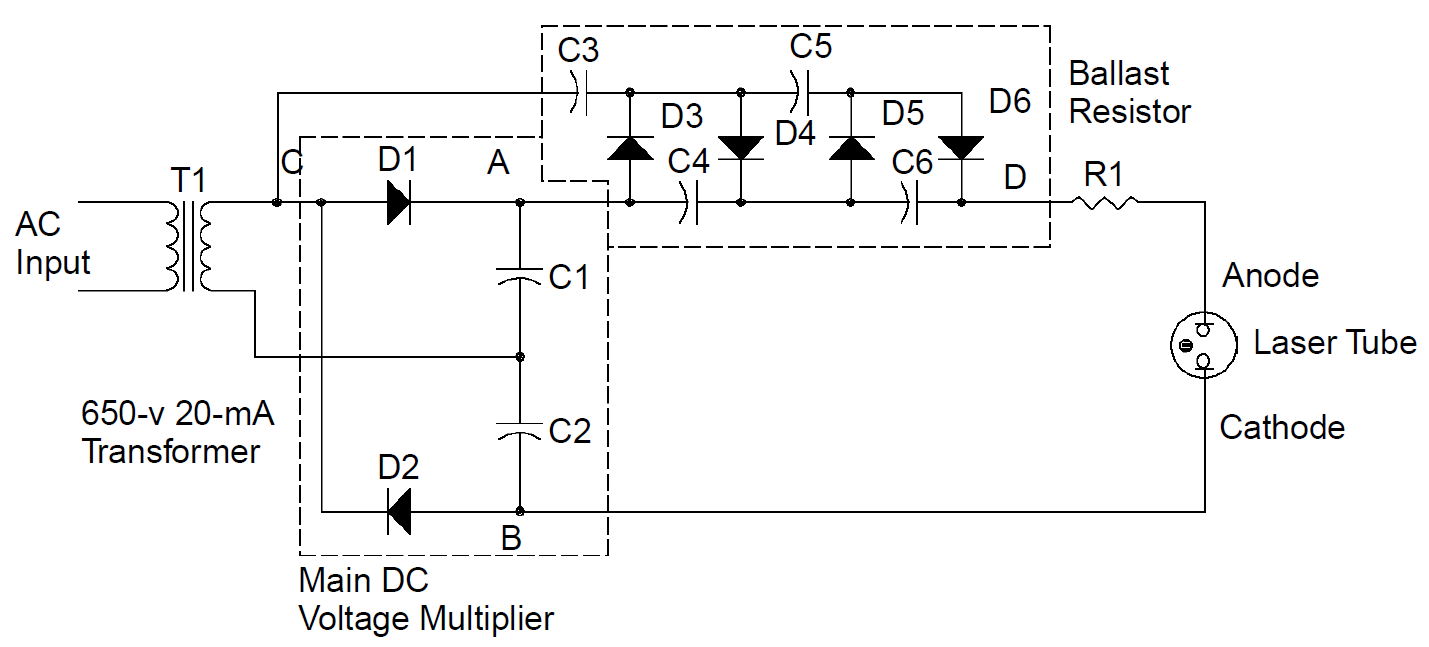
Given the modest current requirements of 5 to 6 mA for an average HeNe tube, power supplies are, generally, relatively simple, supplying a run voltage of about 1500 to 2000 V and a start pulse of up to 10 kV. The start pulse ionizes gas inside the tube to start the discharge. Upon ionization, the resistance of the tube drops, current flows, and the voltage across the tube stabilizes to the run voltage. The schematic for a typical AC-powered supply is shown in Figure 1.1. Incoming line voltage (110 V AC in North America) is stepped up to about 650 V by transformer

Figure 1.1. Helium–neon laser power supply.
T1. When rectified, this becomes 919 V, which is not high enough to run the tube, so it is doubled by a voltage multiplier, consisting of capacitors C1/C2 and diodes D1/ D2. On a positive cycle of the AC line, capacitor C1 charges to 919 V DC (¼650 V AC × 21/2). On a negative cycle, capacitor C2 charges, also to 919 V. Since C1 and C2 are in series, a total voltage of 1838 V is found across terminals A and B on the schematic. Although 1800 V will run most HeNe tubes, it will not initiate the discharge. To do this, a voltage of over 5 kV is required, provided by the multiplier circuit at the top of the diagram consisting of capacitors C3 to C6 and diodes D3 to D6. When the tube is not conducting, this circuit functions as a voltage multiplier, taking AC from the transformer (at point C) and producing a high voltage (of well over 5 kV) at point D (referenced to point B). This high voltage is presented across the tube, which ionizes and begins to conduct current. At that point, current from the main DC voltage multiplier (at terminals A and B) flows through diodes D3 to D6, effectively shorting out the starting circuit. When operating, tube current is limited by ballast resistance R1.
Readers are cautioned that the power supply depicted in Figure 1.1 is a simplified one for the sake of explanation; in reality, the circuitry for a power supply would contain safety features such as bleeder resistors to discharge capacitors when the unit is switched off and may well be designed to use readily available components. For example, capacitors rated at 1000 V are expensive, so each capacitor C1 and C2 would actually be composed of two series capacitors rated at 450 V each, which are much more economical. Similarly, high-voltage diodes in the diagram would probably be constructed of three inexpensive 1-kV diodes in series.
In very long HeNe lasers (some up to 1 m in length) the start pulse provided by a circuit like that described above may still be insufficient to initiate a discharge, in which case a high-voltage pulse can be applied to a tube externally to start it. Generated by a pulse transformer inside the laser head (most lasers of this length have external power supplies) and distributed at several points down the length of the plasma tube, the pulse assists in ionization of the entire length of the tube, which is necessary to initiate a plasma discharge. It is also possible to use RF energy to assist in the generation of the plasma in the same manner (in fact, RF energy can be used as a pump source for the laser discharge instead of a DC current. This approach was popular in the 1960s and 1970s; however, it is rarely used today).
Another trick used with long lasers is to employ a single cathode with two anodes. This approach is used to reduce the electrical path to a manageable length which does not require excessively high voltages to operate or ignite. It is also used in some carbon dioxide laser tubes for the same reasons. In this case, the single cathode connects directly to the power supply, and each anode connects to the supply through a separate ballast resistance. Bear in mind, though, that the majority of HeNe lasers are under 30 cm in length, so do not require special ignition circuitry or techniques.
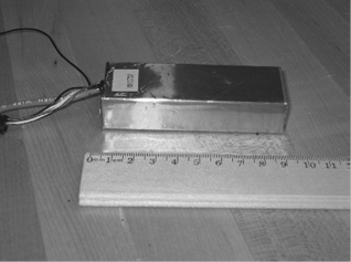
Many modern HeNe supplies use switching technology for a compact unit. An input voltage between 12 and 120 V is rectified and chopped into AC at high frequencies. A step-up transformer is still employed, but given the high frequencies employed, this transformer is quite miniscule and lightweight compared to one operating at 60 Hz. High frequencies also mean that the capacitors used can be much smaller than those used in a lower-frequency design. The result is a compact power supply that is encapsulated in epoxy similar to the unit pictured in Figure 1.2. These units, the standard for a modern HeNe tube supply, have only a few leads protruding, including a high-voltage lead (which connects to the anode of the tube via an external ballast resistance), a ground for the cathode, leads for the input supply, and usually a few leads that configure unit operation, including delayed start for regulatory compliance and interlock inputs. The supply

Figure 1.2. Modern HeNe power supply.
is often encased in copper foil, which serves to prevent the emission of high frequency RF radiation from the supply, which would interfere with nearby equipment and circuitry.
Like any other gas discharge tube, HeNe laser tubes exhibit a feature known as negative resistance. Consider a common resistor that obeys Ohm’s law according to
E = IR
where E is the voltage across the resistance in volts, I the current through the resistance in amperes, and R the resistance in ohms. As current through the resistor is increased, voltage across the device also increases since resistance is fixed. In a gas discharge the effective resistance of the tube decreases as current is increased, so that as the current increases through the tube, voltage across the tube decreases in effect a negative resistance. Unfortunately, this means that a tub connected directly to a power supply will consume current to a point where the resistance of the tube decreases, where, in turn, the tube consumes more current and a runaway condition ensues. The tube then either consumes an extremely high current (usually, catastrophically) or oscillates in an unstable manner.
To correct the problem a (positive) resistance called a ballast resistance is added in series with the tube. This serves to limit the current through the tube to an optimal value and stabilize the discharge. The optimal value of ballast resistance is determined by plotting the voltage-to-current characteristics of the tube and determining the slope of the curve at the desired operating current. The slope of the graph being rise (voltage) over run (current) yields, by definition, resistance. If the optimal operating current is known, the ballast resistance may also be found by measuring the tube voltage at that current.
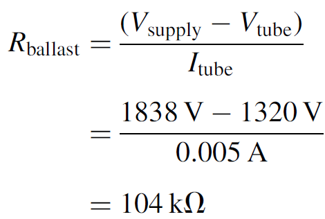
Example 1.1 Ballast Resistance A small HeNe tube is operated from a power supply similar, which has an output of 1838 V. This particular tube has an operating current of 5 mA and a voltage of 1320 V is measured across the tube at that current. The required ballast resistance would be

A ballast resistance of 104 kΩ is required for the tube. Note that when operating, this resistance has 518 V across it and hence dissipates 2.6 W of heat (power = VI).
Ballast resistances typically vary between 25 and 200 kΩ, depending on the tube and power supply and should be mounted as close to the tube as possible (if the tube

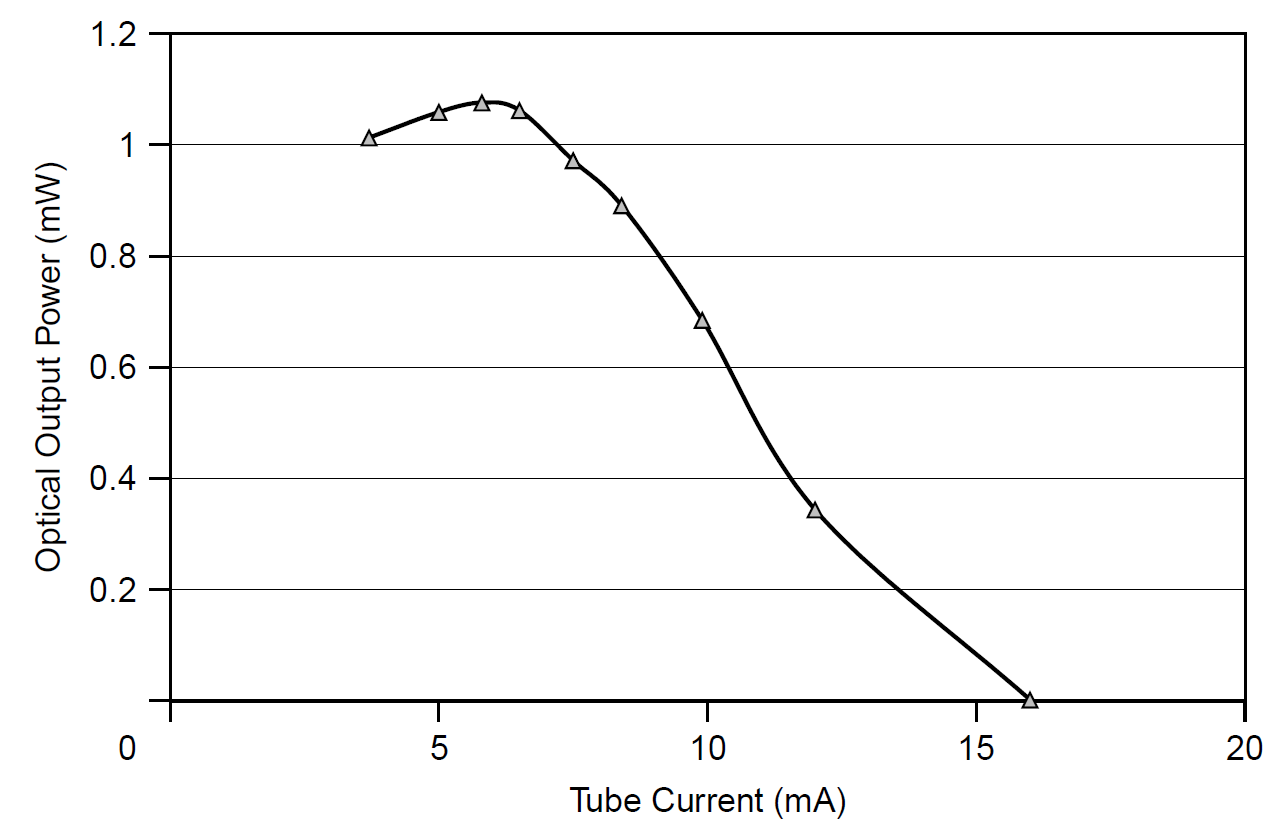
Figure 1.3. Power output versus tube current for a HeNe laser.
is separate from the power supply, it is mounted in the housing with the tube itself) to minimize capacitance, which might tend to cause the tube to oscillate. The operating current desired for a given tube can be determined experimentally by plotting optical output power versus current (the operating current chosen for maximum output power or just below that point) or, in most cases, is specified by the manufacturer for a particular tube. HeNe tubes cannot operate at indefinitely high current, and more current does not translate into more optical power output, since as depicted in Figure 1.3, tube currents above an optimal point actually serve to reduce output power to a point where laser output extinguishes completely. The maximum optical output power is found to occur at a current of 5.8 mA, after which an increase in current leads to a rapid decrease in output power. By 16 mA the laser ceases operation completely (although it becomes quite warm, given the large powers dissipated).
 الاكثر قراءة في مواضيع عامة في الليزر
 اخر الاخبار
اخبار العتبة العباسية المقدسة

الآخبار الصحية


 قسم الشؤون الفكرية يصدر كتاباً يوثق تاريخ السدانة في العتبة العباسية المقدسة
 "المهمة".. إصدار قصصي يوثّق القصص الفائزة في مسابقة فتوى الدفاع المقدسة للقصة القصيرة
 (نوافذ).. إصدار أدبي يوثق القصص الفائزة في مسابقة الإمام العسكري (عليه السلام)


