تاريخ الفيزياء

علماء الفيزياء


الفيزياء الكلاسيكية

الميكانيك

الديناميكا الحرارية


الكهربائية والمغناطيسية

الكهربائية

المغناطيسية

الكهرومغناطيسية


علم البصريات

تاريخ علم البصريات

الضوء

مواضيع عامة في علم البصريات

الصوت


الفيزياء الحديثة


النظرية النسبية

النظرية النسبية الخاصة

النظرية النسبية العامة

مواضيع عامة في النظرية النسبية

ميكانيكا الكم

الفيزياء الذرية

الفيزياء الجزيئية


الفيزياء النووية

مواضيع عامة في الفيزياء النووية

النشاط الاشعاعي


فيزياء الحالة الصلبة

الموصلات

أشباه الموصلات

العوازل

مواضيع عامة في الفيزياء الصلبة

فيزياء الجوامد


الليزر

أنواع الليزر

بعض تطبيقات الليزر

مواضيع عامة في الليزر


علم الفلك

تاريخ وعلماء علم الفلك

الثقوب السوداء


المجموعة الشمسية

الشمس

كوكب عطارد

كوكب الزهرة

كوكب الأرض

كوكب المريخ

كوكب المشتري

كوكب زحل

كوكب أورانوس

كوكب نبتون

كوكب بلوتو

القمر

كواكب ومواضيع اخرى

مواضيع عامة في علم الفلك

النجوم

البلازما

الألكترونيات

خواص المادة


الطاقة البديلة

الطاقة الشمسية

مواضيع عامة في الطاقة البديلة

المد والجزر

فيزياء الجسيمات


الفيزياء والعلوم الأخرى

الفيزياء الكيميائية

الفيزياء الرياضية

الفيزياء الحيوية

الفيزياء العامة


مواضيع عامة في الفيزياء

تجارب فيزيائية

مصطلحات وتعاريف فيزيائية

وحدات القياس الفيزيائية

طرائف الفيزياء

مواضيع اخرى
LASER STRUCTURE
المؤلف:
Mark Csele
المصدر:
FUNDAMENTALS OF LIGHT SOURCES AND LASERS
الجزء والصفحة:
p330
18-4-2016
3327
LASER STRUCTURE
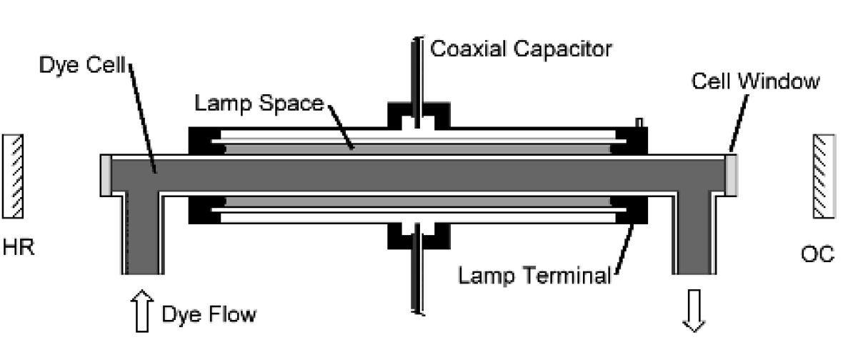
Perhaps the simplest form of a dye laser is the flash lamp-pumped laser, which closely resembles a solid-state laser with a liquid-filled cell instead of a solid crystal rod. Flash lamps may be either linear, with light from the lamp focused onto the dye cell using an elliptical reflector or using a coaxial lamp. The coaxial configuration used in the first lasers of this type is constructed of a space created between the dye cell at the center of the laser and a larger outer jacket, as shown in the cross section of Figure 1.1.
This space between the two quartz tubes is evacuated and filled with a low pressure gas such as xenon. The coaxial approach offers an extremely low inductance path for current if the discharge capacitor is also coaxial (i.e., the entire dye cell and lamp assembly is inserted into the center of a circular capacitor). This approach allows extremely fast discharges, with rise times of well under 1 μs, to be generated. The approach is not limited to the use of a coaxial capacitor, but that configuration certainly produces the fastest discharges.
Other configurations for a flash lamp-pumped dye laser include a slab configuration in which the dye cell is formed between two slabs of glass that have a different index of refraction than the dye solution between the slabs. Total internal reflection confines light within the cavity, producing a long optical path and hence large amplification. This is similar to the confinement provided by various guiding layers in a practical semiconductor diode laser. In a flash lamp-pumped dye laser, circulation of the dye is required to keep the temperature of dye across the cell consistent. If one region of the dye is warmer than another region, a thermal gradient develops, with the result being a difference of indexes of refraction of liquid in the dye cell which spoil the Q of the cavity, preventing laser oscillation.
Flash lamp-pumped dye lasers feature large pulse energies and are a useful source for opthalmological procedures, where they may be used for retinal photocoagulation.

Figure 1.1. Flash lamp-pumped dye laser configuration.

Figure 1.2. Laser-pumped dye laser.
However, pulse rate is severely limited to the rate at which dye can flow through the dye cell to remove heat and suppress thermal gradients that may occur. In addition, electrical discharge paths in a flash lamp-pumped dye laser are critical and must be manufactured with extremely low inductance. The other type of dye laser is pumped by another laser, such as an excimer or nitrogen laser as in Figure 1.2. These lasers are fairly simplistic and, compared to flash lamp pumped types, exhibit unusually high gain, allowing the use of a short dye cell.
In this arrangement, the pump laser beam is focused to a line on a dye cell using a cylindrical lens, as shown in Figure 1.3, in which the focused beam from a nitrogen or excimer pump laser strikes the side of a dye cell exciting dye molecules along the length of the cell. In most cases it is possible to operate the dye laser super radiantly by focusing the pump laser tightly onto the dye cell, but this is not desirable since a dye laser operated in such a way is not tunable, losing the major advantage of this laser over other lasers, so pump light is not focused so tightly that super radiance occurs. Pump light striking the dye cell excites dye molecules in a narrow channel physically just inside the dye cell itself: Penetration of the pump light into the cell is minimal, and essentially all is absorbed within the first few millimeters of dye within the cell.
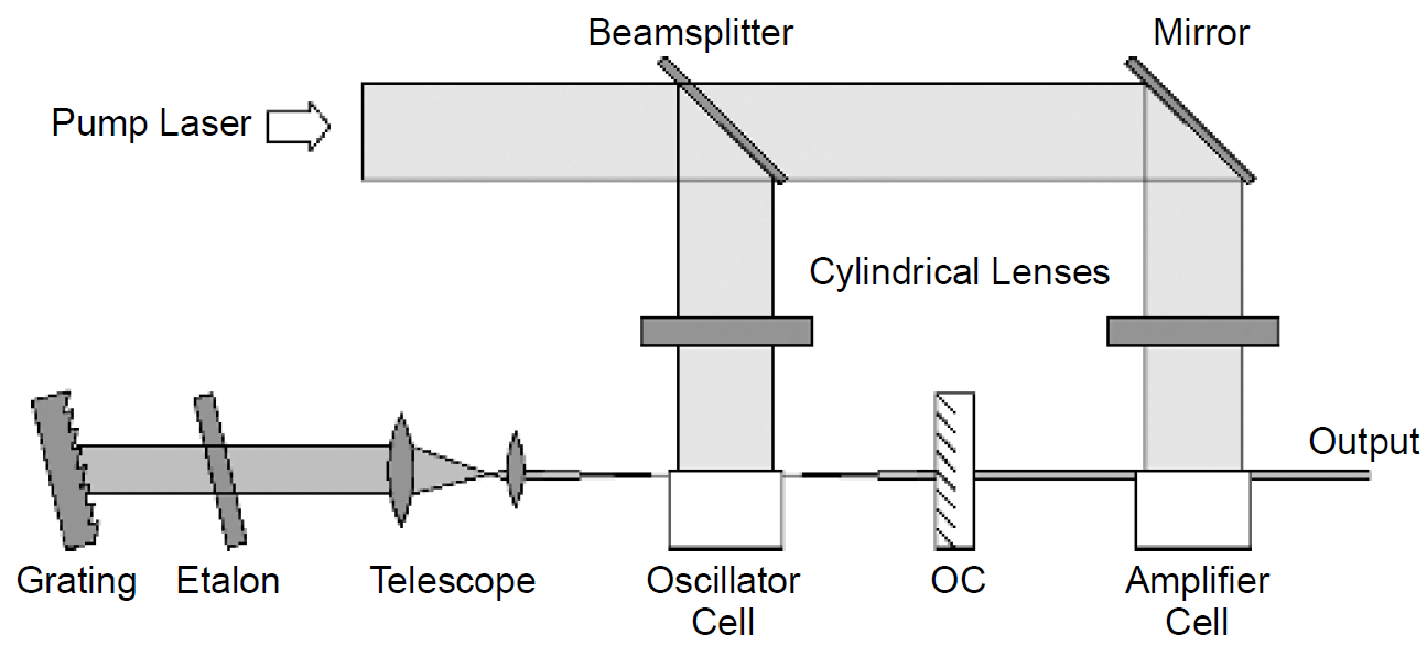
Optics for a laser-pumped dye laser usually consist of an output coupler and a diffraction grating. Although a simple mirror (HR) could be used in the cavity, a grating is invariably used to allow tuning of the laser across the wide gain bandwidth of the laser, the biggest advantage of a dye laser. In a practical dye laser a beam expander consisting of two lenses is placed between the dye cell and the diffraction grating to utilize more of the grating area. An etalon may also be placed in the optical path to reduce spectral width. Finally, a MOPA configuration may be used in which a separate amplifier is placed in front of the oscillator (complete with wave-

Figure 1.3. Excited dye cell.
length selector). The configuration for a complete dye laser with narrow spectral output width is shown in Figure 1.4.
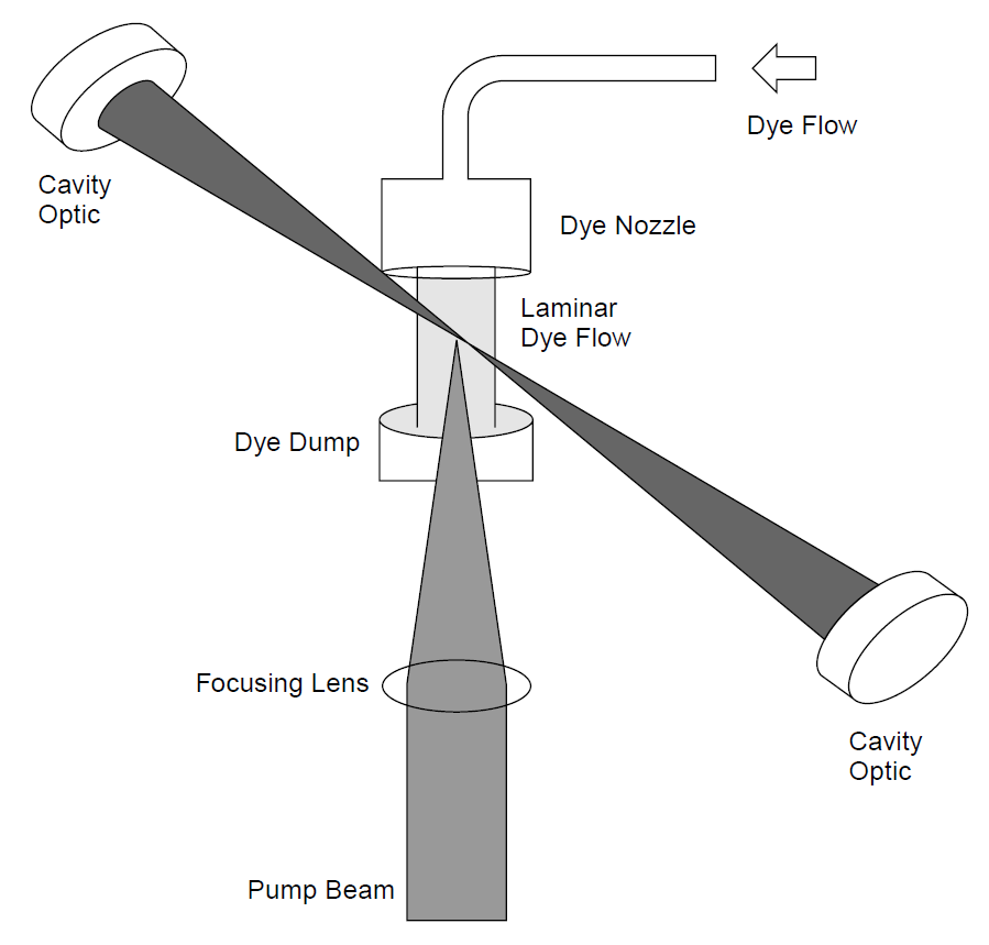
The pump laser is usually a nitrogen or excimer laser emitting in the UV range, but frequency-doubled YAG lasers may also be used. Because the pump laser is pulsed, the dye laser also has a pulsed output, but it is possible to build a CW dye laser pumped by a CW laser source such as an ion laser. In this case the biggest problem becomes heat management and degradation of the dye itself. Both problems are alleviated by forming the dye into a continually flowing sheet of liquid called a laminar flow. Flowing dye is pumped through a nozzle to create a broad, flat stream

Figure 1.4. Optics for a dye laser.

Figure 1.5. CW dye laser.
onto which pump laser light, usually from an argon-ion laser given that many laser dyes absorb strongly in the violet-to-green band where the argon-ion laser has the strongest output, is focused by a lens (or a concave mirror) onto the surface of the flowing dye. In a manner similar to that of the laser-pumped arrangement described previously, a column of excited dye molecules serves as the gain medium, which, is off-axis (usually at the Brewster angle) from the axis of the optical resonator. A typical CW dye laser arrangement is shown in Figure 1.5. Like most dye lasers, intracavity wavelength selectors are also often included (although they are no shown in the figure).
Aside from heat removal (required when the pump laser is a 10-W CW argon-ion laser!), dye flow helps suppress the effects of triplet absorption in the dye by ensuring a fresh supply of dye in the area irradiated by pump laser light. Fast dye flow is hence required to ensure that dye molecules are exchanged before triplet absorption becomes problematic and affects lasing action.
 الاكثر قراءة في مواضيع عامة في الليزر
 اخر الاخبار
اخبار العتبة العباسية المقدسة

الآخبار الصحية


 قسم الشؤون الفكرية يصدر كتاباً يوثق تاريخ السدانة في العتبة العباسية المقدسة
 "المهمة".. إصدار قصصي يوثّق القصص الفائزة في مسابقة فتوى الدفاع المقدسة للقصة القصيرة
 (نوافذ).. إصدار أدبي يوثق القصص الفائزة في مسابقة الإمام العسكري (عليه السلام)


